


Quick Research
Generate reliable direction feasibility study reports for your R&D in just a few steps.

Technical Q&A
Discover and master advanced knowledge NOW. Basics, ideas, possibilities, all at once.

Find Solutions
As an expert in R&D theories, this can generate solutions to your technical problems instantly.

Evaluate Feasibility
Analyze your overall solution with one click, know your potential R&D risks in advance.

Monitor Landscape
Get weekly tech updates, stay abreast of the latest tech innovations and key insights.
Splicing type swing rod of circular weaving machine
A spliced, circular loom technology, applied in circular looms, looms, textiles, etc.
- Summary
- Abstract
- Description
- Claims
- Application Information
AI Technical Summary
Problems solved by technology
Method used
Image


Examples
Embodiment 1
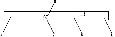
[0021] Such as figure 1 , figure 2 and image 3As shown, a circular loom splicing swing rod, the front end of which is provided with a swing rod slider axle 1 for installing the slider wheel, and the slider wheel is connected to the driving cam of the circular loom to obtain the swing power of the swing rod. The end of the swing rod is provided with a heald belt connecting bearing 2, and the middle and front part is provided with a rotating shaft 3 connected with the aluminum seat. The two ends of the rotating shaft 3 are respectively sleeved with aluminum seat bearings. The swing rod starts from the middle front to the end. The width gradually becomes smaller. The swing rod of the circular loom is a split structure, including three splicing sections, namely the front section 4, the middle section 5 and the end section 6. The axle 1 is located on the front section 4, and the heddle belt connection bearing 2 and the rotating shaft 3 are located on the end section 6 and the...
Embodiment 2
[0024] In the inter-segment connection structure, only the protruding laminated plates 7 at both ends of the middle section 5 are provided with side baffles 10, and the side baffles 10 are all arranged in pairs, and are located on both sides of the protruding laminated plates 7 on the middle section 5. . When the middle section 5 is connected with the front section 4 and the end section 6, only the protruding laminated plates 7 on the front section 4 and the end section 6 are inserted between the pair of side baffles 10 at both ends of the middle section 5, and then locked with bolts, The splicing between segments can be completed quickly. All the other are with embodiment 1.
Embodiment 3
[0026] The swing rod of the circular loom includes four splicing sections, which are the front section 4, the middle front section, the middle rear section and the end section 6. All the splicing sections are connected sequentially through the inter-segment connection structure, and the swing bar slider wheel shaft 1 is located on the front section 4. The heddle belt connecting bearing 2 and the rotating shaft 3 are respectively located on the end section 6 and the middle front section. The middle and rear sections are purely injection molded, and there are no moving parts on this section. Dividing the pendulum into four sections can further shorten the length of each section, thereby further reducing the manufacturing cost of each section. When the pendulum is partially damaged, the equipment recovery can be completed at a lower maintenance cost. All the other are with embodiment 1.
PUM
 Abstract
Description
Claims
Application Information
 - R&D Engineer
- R&D Manager
- IP Professional
- Industry Leading Data Capabilities
- Powerful AI technology
- Patent DNA Extraction
Browse by: Latest US Patents, China's latest patents, Technical Efficacy Thesaurus, Application Domain, Technology Topic, Popular Technical Reports.
© 2024 PatSnap. All rights reserved.Legal|Privacy policy|Modern Slavery Act Transparency Statement|Sitemap|About US| Contact US: help@patsnap.com