Conveying system, spinning equipment with the same and method for staring spinning equipment
A technology of transmission system, textile equipment, applied in the field of transmission system
- Summary
- Abstract
- Description
- Claims
- Application Information
AI Technical Summary
Problems solved by technology
Method used
Image
Examples
Embodiment Construction
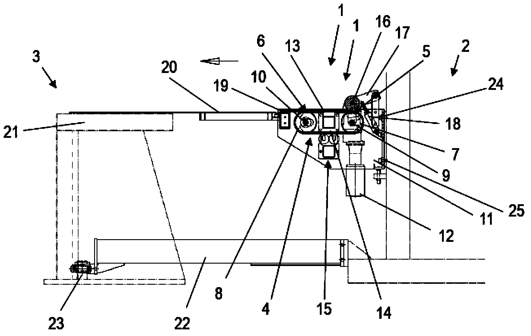
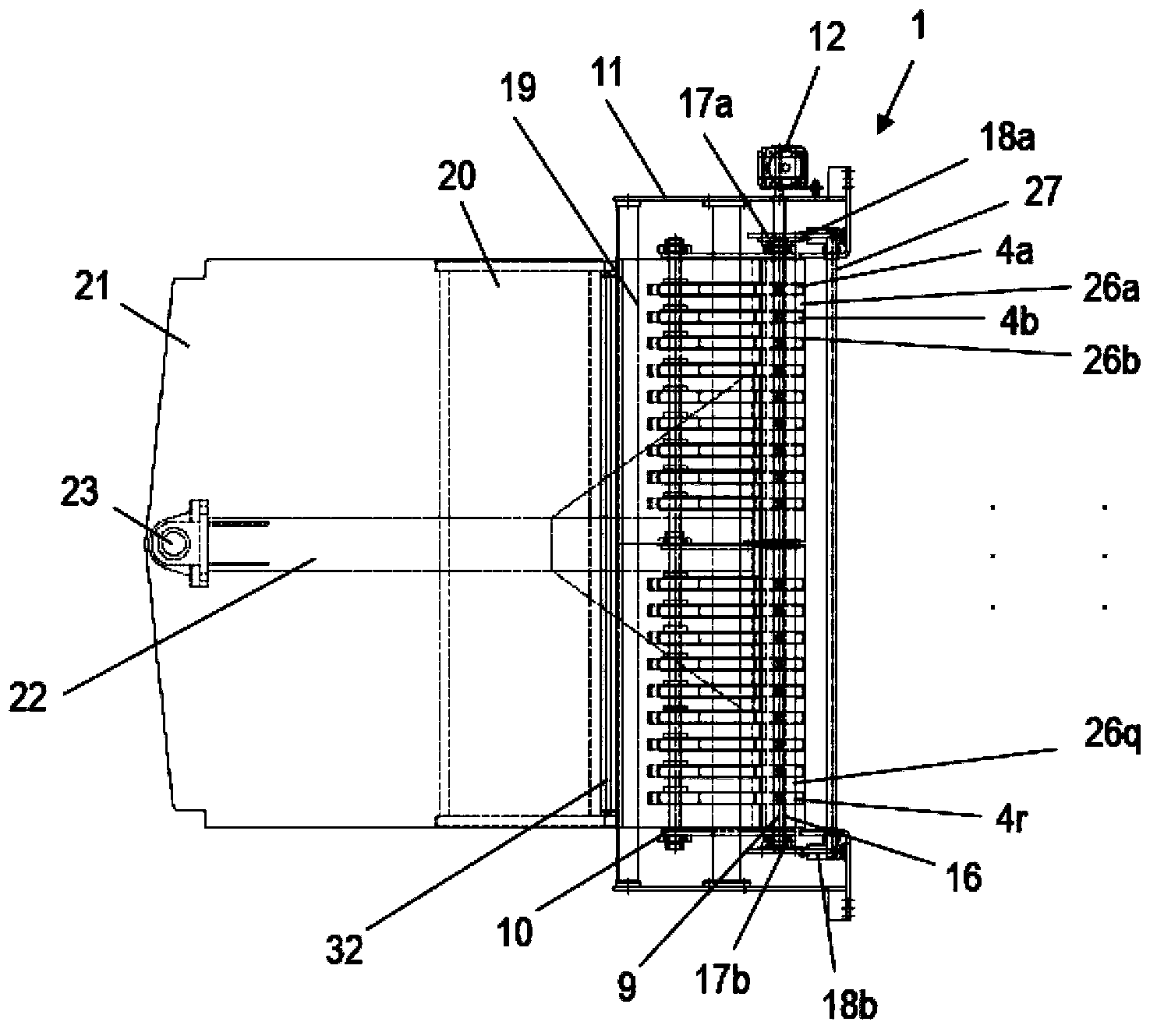
[0045] exist figure 1 A side view of the conveyor system 1 is shown in . The conveyor system 1 is located between two adjacent plant parts: the uncoiling station 2 and the cutting device 3 . In this case, the conveyor system 1, the uncoiling station 2 and the cutting device 3 are part of a textile Image 6 and 7 is schematically shown in and is used for processing thin and sticky ply strips.
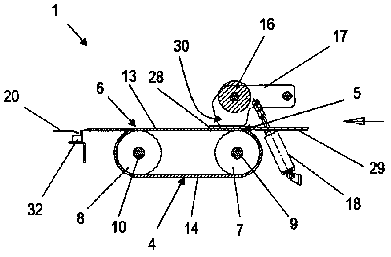
[0046] The conveyor system 1 has a plurality of conveyor belts 4 arranged parallel to one another, which are guided in a loop at a conveyor start 5 and a conveyor end 6 via deflection wheels 7 , 8 . In this case, the deflecting wheels 7 , 8 are mounted rotatably via shafts 9 , 10 in the frame 11 of the conveyor system 1 , respectively. In this case, the shaft 9 arranged at the delivery start 5 can be driven via a drive 12 . The movement of the shaft 9 is transmitted via the deflection pulley 7 to the conveyor belt 4 and to the deflection pulley 8 with its shaft 10 . The strip of ma...
PUM
 Abstract
Description
Claims
Application Information
 - R&D
- Intellectual Property
- Life Sciences
- Materials
- Tech Scout
- Unparalleled Data Quality
- Higher Quality Content
- 60% Fewer Hallucinations
Browse by: Latest US Patents, China's latest patents, Technical Efficacy Thesaurus, Application Domain, Technology Topic, Popular Technical Reports.
© 2025 PatSnap. All rights reserved.Legal|Privacy policy|Modern Slavery Act Transparency Statement|Sitemap|About US| Contact US: help@patsnap.com


