Granular material flow control device

A flow control device, a technology for granular materials, applied in the direction of flow control, conveyor control device, non-electric variable control, etc., can solve the problem of clogging the rod valve, unable to achieve accurate material flow control, easy to burn the push rod electric components, etc. problem to avoid stuck

Inactive Publication Date: 2014-12-17
青岛中联水泥有限公司
View PDF0 Cites 1 Cited by
  • Summary
  • Abstract
  • Description
  • Claims
  • Application Information

AI Technical Summary

Problems solved by technology

Due to the high hardness of the particles, sometimes the stick valve is blocked, the push rod cannot move, and the electric parts of the push rod are easy to be burned. In addition, it is impossible to achieve accurate control of the material flow.

Method used


Image

  • Granular material flow control device
  • Granular material flow control device
  • Granular material flow control device

Examples


Embodiment Construction

[0012] Below in conjunction with accompanying drawing embodiment, the present invention will be further described:

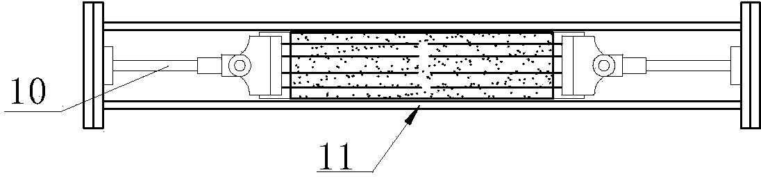
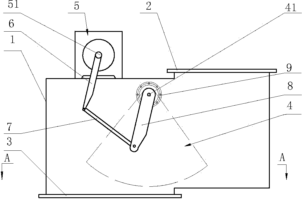
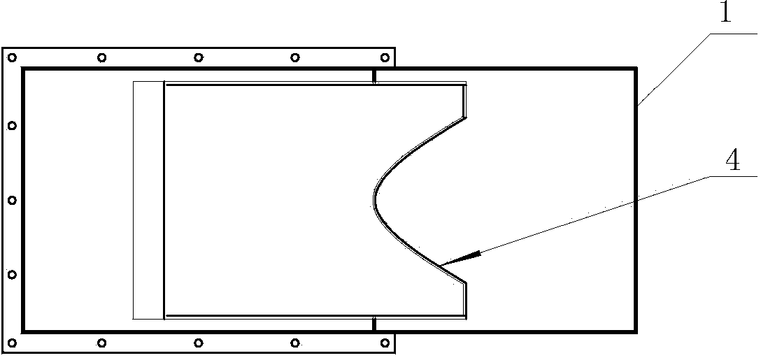
[0013] Such as figure 2 , image 3 As shown, it includes a housing 1, a feed hole 2, and a discharge hole 3. An arc-shaped valve core 4 is arranged inside the housing 1. The arc-shaped valve core 4 is fixedly mounted on a rotating shaft 41, and the two ends of the rotating shaft 41 are supported by bearings 9. On the casing 1, an electric actuator 5 capable of outputting torque is arranged on the casing 1. One end of the crank 6 is fixedly connected with the output shaft 51 of the electric actuator 5, and the other end of the crank 6 is fixedly installed with the connecting rod 7 and the one end of the rotating shaft 41. Rod 8 constitutes a crank swing mechanism.

[0014] Working process of the present invention is as follows:

[0015] Such as figure 2 As shown, the torque output by the electric actuator 5 sequentially passes through the crank 6 and the co...


PUM


Abstract

The invention discloses a granular material flow control device, which comprises a shell, a feeding hole and a discharge hole, wherein the interior of the shell is provided with an arc-shaped valve core; the arc-shaped valve core is fixedly arranged on a revolving shaft; both ends of the revolving shaft are supported onto the shell through bearings; the shell is provided with an electric actuator capable of outputting torque; one end of a crank is fixedly connected with the output shaft of the electric actuator; the other end of the crank, a connecting rod and a swing rod fixedly arranged at one end of the revolving shaft form a crank swing rod mechanism. The granular material flow control device disclosed by the invention has the beneficial effects that material blocking is avoided, and material flow control can be realized.

Description

technical field [0001] The invention relates to the field of material flow control, and specifically refers to a granular material flow control device. Background technique [0002] In terms of granular material flow control, the prior art adopts a material control device with an electric push rod and a rod valve. Control the material flow through the rod gap. Due to the high hardness of the particles, sometimes the rod valve is blocked, the push rod cannot move, and the electric parts of the push rod are easy to be burned. In addition, the accurate control of the material flow cannot be realized. Contents of the invention [0003] The technical problem to be solved by the present invention is to provide a granular material flow control device that uses a rotor rotating body valve core to effectively avoid sticking of rod valve particles. [0004] The technical solution adopted by the present invention to solve the technical problem is: a granular material flow control d...

Claims


Application Information

Patent Timeline
Patent Type & Authority Applications(China)
IPC IPC(8): B65G43/00G05D7/00
Inventor 孟宪恒李浩
Owner 青岛中联水泥有限公司
Why Eureka
Try Eureka