
Overheat protection circuit and overheat protection method

A technology of overheat protection circuit and protection switch, which is applied in the direction of emergency protection circuit devices, circuits, and protection reacting to overcurrent, etc., which can solve problems such as abnormal overheating and achieve the effect of preventing abnormal overheating

Inactive Publication Date: 2014-12-10
YAZAKI CORP
View PDF8 Cites 0 Cited by
  • Summary
  • Abstract
  • Description
  • Claims
  • Application Information

AI Technical Summary

Problems solved by technology

[0004] However, when FETs as semiconductors are used instead of conventional mechanical relays, abnormal overheating may occur due to some malfunctions other than overcurrent
Even if the FET has an over-temperature interrupt function, the same phenomenon may occur

Method used


Image

  • Overheat protection circuit and overheat protection method
  • Overheat protection circuit and overheat protection method
  • Overheat protection circuit and overheat protection method

Examples


Embodiment Construction

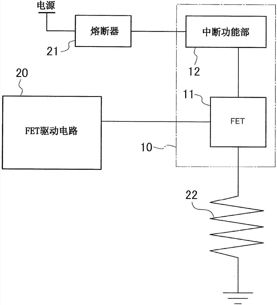
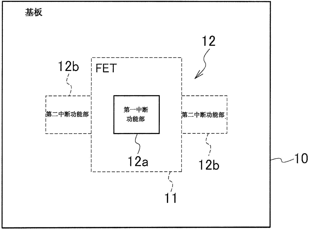
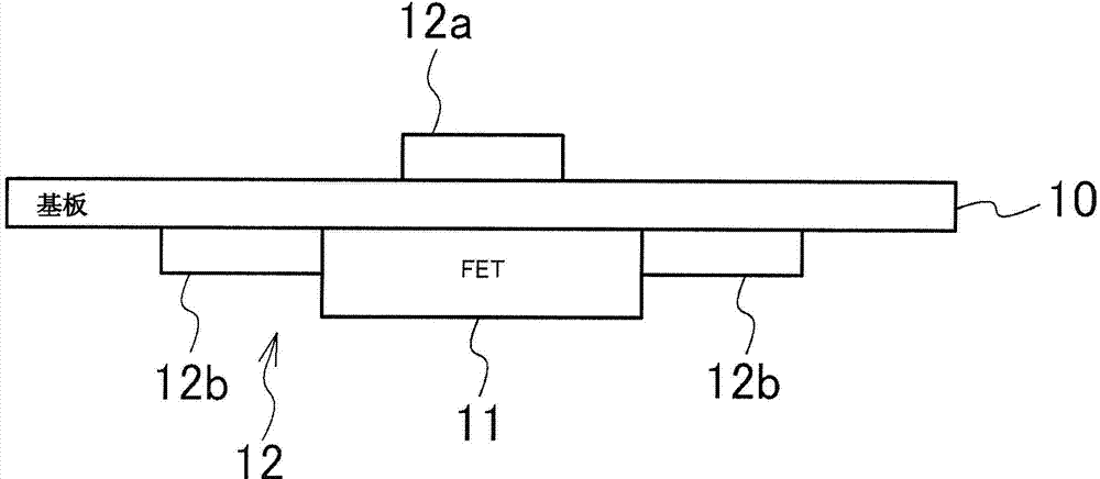
[0027] Refer below Figures 1 to 3 Embodiments of the overheat protection circuit of the present invention are described in detail. First, if figure 1 As shown, the overheat protection circuit includes an interrupt function section 12 arranged close to a FET (Field Effect Transistor) 11 which is a switching element mounted on a substrate 10 .

[0028] In the figure, reference numeral 20 is a FET drive circuit that switches ON / OFF of the FET 11; reference numeral 21 is a fuse that interrupts power from the power source when a current greater than a prescribed value flows; and Reference numeral 22 shows a load resistance. A MOSFET (Metal Oxide Semiconductor Field Effect Transistor) or a C-MOSFET (Complementary MOSFET) can be used as the FET 11 . Either P-channel type or N-channel type can be used for both MOSFET and C-MOSFET.

[0029] figure 1 A connection is shown in which a fuse 21 , a FET 11 loaded on a substrate 10 , and an interrupt function section 12 are provided bet...


PUM


Abstract

An overheat protection circuit for protecting a switching element 11 from abnormal overheat is provided, the switching element configured to supply electric power from a power source to a side of a load 22, including an interruption function part 12 configured to detect a layer short inside the switching element and configured to detect temperature of the switching element, wherein the interruption function part is configured to interrupt the electric power supplied from the power source to the side of the load at an input part of the switching element, when detecting the layer short and detecting that the temperature exceeds a predetermined value.

Description

technical field [0001] The present invention relates to an overheat protection circuit and an overheat protection method suitable for preventing abnormal overheating of switching elements. Background technique [0002] Conventionally, switching elements such as FETs (Field Effect Transistors) are often used instead of mechanical relays in devices that supply power from a power source to a load side. [0003] As a measure to avoid abnormal overheating in the FET, in circuit components that supply power from the power source to the load side through the FET, and a fuse is provided in the upstream side of the FET, it is typical, for example, when an overcurrent flows , the fuse melts to interrupt the overcurrent. [0004] However, when a FET as a semiconductor is used instead of a conventional mechanical relay, abnormal overheating may occur due to some malfunction other than overcurrent. Even if the FET has an overtemperature interrupt function, the same phenomenon may occur...

Claims


Application Information

Patent Timeline
Patent Type & Authority Applications(China)
IPC IPC(8): H03K17/0814H02H3/08H03K17/082
CPCH02H7/222H03K2017/0806H02H5/04H03K17/08142H03K17/0822H02H5/047
Inventor 山下刚花冈康隆
Owner YAZAKI CORP
Learn More