
Cooling unit for traction converter

A traction converter, cooling unit technology, applied in cooling/ventilation/heating transformation, AC power input conversion to AC power output, electrical components, etc., can solve the problem of reducing the reliability of cooling units, falling off the protective bottom plate, and high air resistance problems, to achieve the effect of improving maintenance work efficiency, facilitating use and maintenance, optimizing matching and integration

Active Publication Date: 2014-12-10
CRRC DALIAN INST CO LTD
View PDF11 Cites 6 Cited by
  • Summary
  • Abstract
  • Description
  • Claims
  • Application Information

AI Technical Summary

Problems solved by technology

[0003] (1) In the load-bearing frame of the existing cooling unit, the top load-bearing installation frame and the vertical load-bearing column are welded together. Since all parts are made of thin plates, the deformation of multiple long rod-shaped parts is large after welding together, and it is difficult to ensure vertical load-bearing Dimensions of each mounting hole on the column
When the bottom plate and the vertical load-bearing column are installed, it is very easy to form prestress on the connected parts and affect the overall strength
[0004] (2) The FSA filter used in the cooling unit filter has high air resistance at the same flow rate, and the filtering effect is not good
Once all the mounting bolts on the protective bottom plate fall off due to special reasons such as abnormal vibration, the protective bottom plate will fall off and enter the track, which will pose a serious threat to the safe operation of the train.
[0006] (4) Partial parts of the cooling unit fan box and collector mounting plate are cracked, reducing the reliability of the cooling unit and causing safety hazards

Method used


Image

  • Cooling unit for traction converter
  • Cooling unit for traction converter
  • Cooling unit for traction converter

Examples


Embodiment Construction

[0034] The present invention will be further described below in conjunction with accompanying drawing.

[0035] In order to realize the safe operation of EMUs with a speed of 350 kilometers per hour, according to the overall technical conditions of EMUs with a speed of 350 kilometers per hour, the technical conditions of water-cooled converters and cooling units of 6500V IGBT, and the appearance of cooling units for traction converters of existing EMUs The common faults of the traction converter have been innovatively designed.

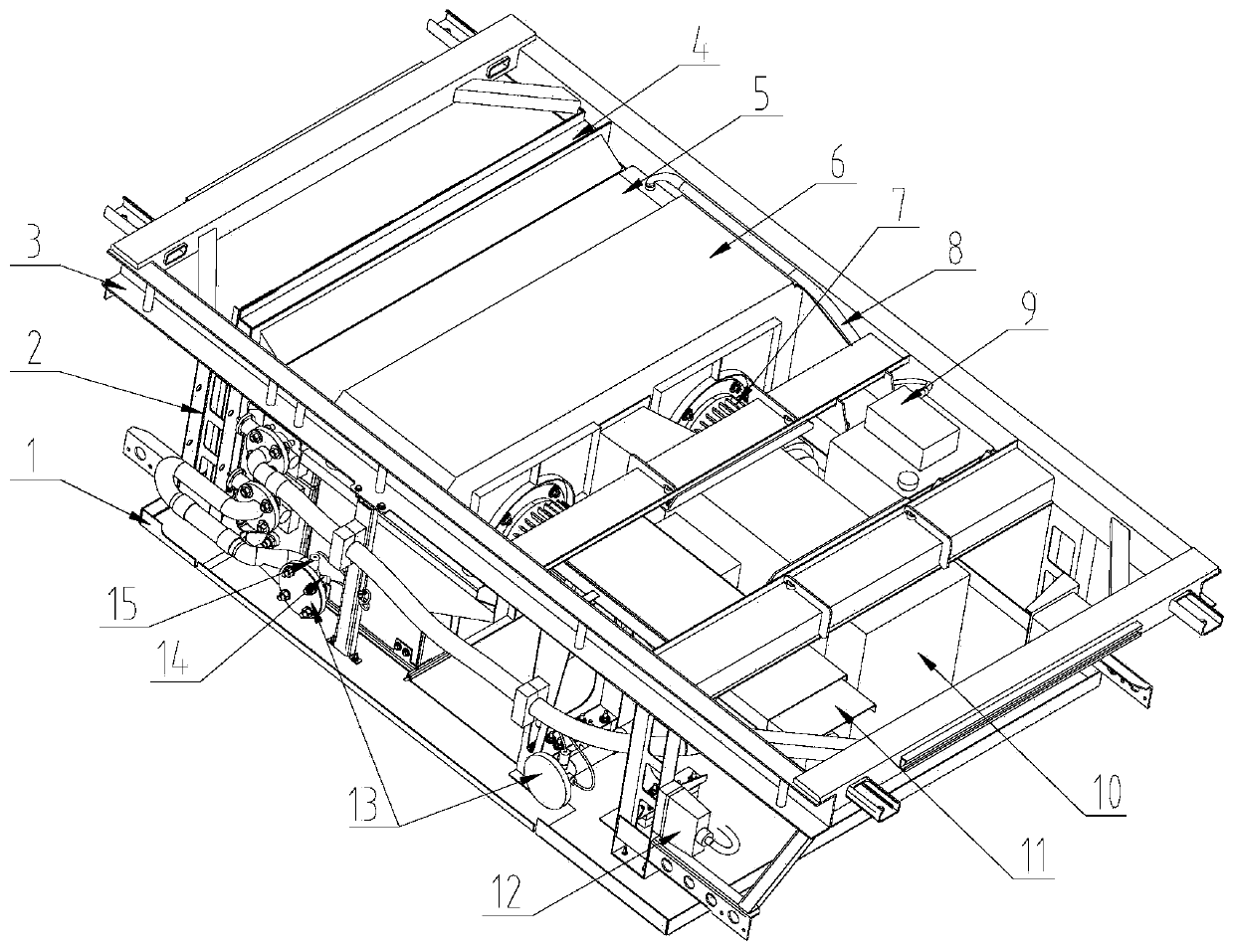
[0036] A traction converter cooling unit (such as figure 1As shown), including assembly of protective bottom plate 1, assembly of vertical load-bearing column 2, assembly of top load-bearing installation frame 3, assembly of filter 4, assembly of radiator 5, assembly of fan duct 6, assembly of fan unit 7, assembly of expansion tank 9, series connection Resonant inductor assembly 10, water pump assembly 11, water system auxiliary circulation pipeline ...


PUM


Abstract

The invention discloses a cooling unit for a traction converter. According to the cooling unit, by carrying out the simulated analysis on the flow behavior of cooling air and the flow behavior of water, the resistance property of an air filter, a radiator, a blower case body and other components is determined; by the adoption of the matching technology, a blower of a cooling air system is guaranteed to work in a high-efficiency working area, and a cooling water system is guaranteed to work in a water pump high-efficiency working area, so that the optimized matching among heat exchange capability, auxiliary power consumption and noise is realized. On the given working condition, the heat exchange requirement of the cooling systems is satisfied; the dust filtration and water filtration efficiency of a filter is improved, and air resistance is lowered simultaneously, so that auxiliary power consumption is reduced; the adopted security measures can prevent a baseplate of the cooling unit from dropping off so as to improve both reliability and security; the cooling unit is suitable for a motor train unit at the speed of 300-350 kilometers per hour, and can further be suitable for the motor train unit in other speed grades by variant design.

Description

technical field [0001] The invention relates to the technical field of cooling systems for train sets. Background technique [0002] At present, the cooling units of traction converters of electric multiple units in my country have the following shortcomings: [0003] (1) In the load-bearing frame of the existing cooling unit, the top load-bearing installation frame and the vertical load-bearing column are welded together. Since all parts are made of thin plates, the deformation of multiple long rod-shaped parts is large after welding together, and it is difficult to ensure vertical load-bearing The size of each mounting hole on the column. After the bottom plate and the vertical load-bearing column are installed, it is very easy to form prestress on the connected parts and affect the overall strength. [0004] (2) The FSA filter used in the cooling unit filter has high air resistance under the same flow rate, and the filtering effect is not good. That is to say, it needs...

Claims


Application Information

Patent Timeline
Patent Type & Authority Applications(China)
IPC IPC(8): H02M5/00H05K7/20
CPCH05K7/20H02M5/00
Inventor 刘俊杰孔丽君陈朝春李永富贾洪洋郭华仲
Owner CRRC DALIAN INST CO LTD
Learn More