
A detachable heat exchanger plate bundle composed of all-welded plates and tubes

A heat exchanger, detachable technology, applied in the field of heat exchanger design and manufacturing, can solve the problems of non-detachable, easy scaling, high working pressure, etc., and achieve the effect of compact structure, small footprint, and easy processing and manufacturing

Active Publication Date: 2016-04-13
GANSU LANPEC TECH +1
View PDF6 Cites 0 Cited by
  • Summary
  • Abstract
  • Description
  • Claims
  • Application Information

AI Technical Summary

Problems solved by technology

The advantage of the detachable heat exchanger is that it is more convenient to disassemble and assemble, but the disadvantage is that the pressure bearing capacity is low, so it is suitable for heat exchange of low-pressure, easy-to-fouling, high-viscosity coefficient media
The advantage of the fully welded heat exchanger is that it has high pressure and temperature resistance, and the disadvantage is that it cannot be disassembled, so it is impossible to clean the dust and dirt accumulated on the plates
[0003] Plate heat exchangers are usually used in petroleum, petrochemical, coal chemical and other fields. In production, such a working condition is often encountered. One medium has a small viscosity coefficient, but the working pressure or temperature is high, and the other The second kind of medium has low working pressure, but it is easy to accumulate dust, scale or block the channel due to the large viscosity coefficient.
Under these conditions, existing fully welded heat exchangers often clog (even with wide runner plates) and existing detachable heat exchangers leak
Therefore, the existing heat exchangers cannot meet this specific working condition
Whether it is clogging or leakage, it will cause the failure of the heat exchanger, which will bring serious safety hazards to daily production.

Method used


Image

  • A detachable heat exchanger plate bundle composed of all-welded plates and tubes
  • A detachable heat exchanger plate bundle composed of all-welded plates and tubes
  • A detachable heat exchanger plate bundle composed of all-welded plates and tubes

Examples


Embodiment Construction

[0024] The present invention and its effects will be further described below in conjunction with the accompanying drawings.

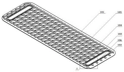
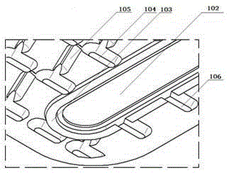
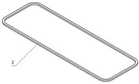
[0025] refer to Figure 1 to Figure 6c , a detachable heat exchanger plate bundle composed of all-welded plate tubes. First, holes are opened near the two opposite sides and near both ends of the corrugated plate sheet 1 to form a medium inlet and outlet 102; then the two corrugated plates are The sheets are stacked together so that the convex corrugations on them are in contact with each other; secondly, the inlay 2 is welded between the two corrugated sheets to form a fully welded sheet tube; again, the sealing gasket groove 103 between the two sheet tubes and at the entrance and exit of the medium Equipped with rubber sealing gasket 3 to form a heat exchanger plate bundle. Finally, the plate bundle is fixed together by means of bolt connection, thereby forming a detachable heat exchanger plate bundle.

[0026] The corrugated sheet 1 is formed by ...


PUM


Abstract

A detachable heat exchanger plate bundle composed of all-welded plate tubes, including corrugated plates and inserts, and the corrugated plates have holes at their near ends respectively, and the holes are a medium inlet and outlet. A sealing gasket groove is set at the entrance and exit of the medium; the two corrugated plates are buckled together, and the convex corrugations on them are in contact with each other, and the surrounding strips are added, and welded together to form a fully welded plate tube. A channel for fluid circulation is formed in the tube; two of the plate tubes are stacked together, and a sealing gasket is fitted in the sealing gasket groove to form a plate bundle, and the channel formed between the plate tubes is another A channel for fluid circulation; the plate bundles are fixed together by bolts, thereby forming a detachable heat exchanger plate bundle. The invention solves the problem of easy blockage of plate bundles in actual work.

Description

technical field [0001] The invention belongs to the technical field of design and manufacture of heat exchangers, in particular to a heat exchanger corrugated plate bundle, in particular to a detachable heat exchanger plate bundle composed of fully welded plate tubes. Background technique [0002] According to different assembly forms, heat exchangers can be divided into two types: detachable and fully welded. The advantage of the detachable heat exchanger is that it is convenient to disassemble and assemble. The disadvantage is that the pressure bearing capacity is low, so it is suitable for heat exchange of low pressure, easy to scale, and high viscosity medium. The advantage of the all-welded heat exchanger is that it has high pressure and temperature resistance, and the disadvantage is that it cannot be disassembled, so it is impossible to clean the dust and dirt accumulated on the plates. [0003] Plate heat exchangers are usually used in petroleum, petrochemical, coal...

Claims


Application Information

Patent Timeline
Patent Type & Authority Patents(China)
IPC IPC(8): F28D9/00F28F3/02F28F3/08F28F3/10
Inventor 张延丰常春梅胡国栋唐海
Owner GANSU LANPEC TECH
Learn More