High-speed elevator speed limiter

A technology for high-speed elevators and speed limiters, which is applied in elevators, transportation, and packaging. It can solve the problems that the friction wheels cannot guarantee simultaneous braking, the action speed of the speed limiter is inaccurate, and the parts are deformed due to uneven force. Speed ​​limit effect, accurate action speed, uniform force effect

Active Publication Date: 2014-12-10
HEBEI DONGFANG FUDA MACHINERY
View PDF6 Cites 4 Cited by
  • Summary
  • Abstract
  • Description
  • Claims
  • Application Information

AI Technical Summary

Problems solved by technology

[0005] 1. The two friction wheels cannot guarantee simultaneous braking, which will cause inaccurate action speed of the speed limiter and large dispersion
In addition, when the two friction wheels brake differently, it may cause uneven deformation of the parts, and in severe cases, the speed limiter will fail.
[0006] 2. The speed limiter needs to be equipped with two switches, one is used to detect the electrical speed, and the other is forcibly disconnecting the circuit during mechanical action, which is costly
[0007] 3. The above-mentioned patented speed limiter, the main shaft cannot rotate, and the encoder cannot be connected, so there are great limitations in using it for high-speed elevators

Method used


Image

  • High-speed elevator speed limiter
  • High-speed elevator speed limiter
  • High-speed elevator speed limiter

Examples


Embodiment Construction

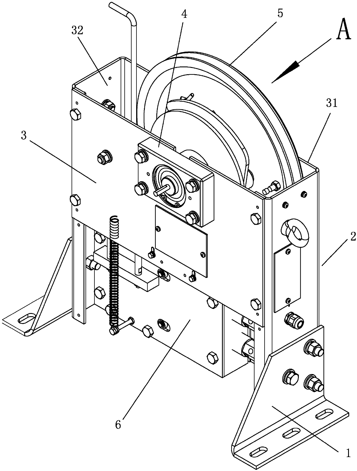
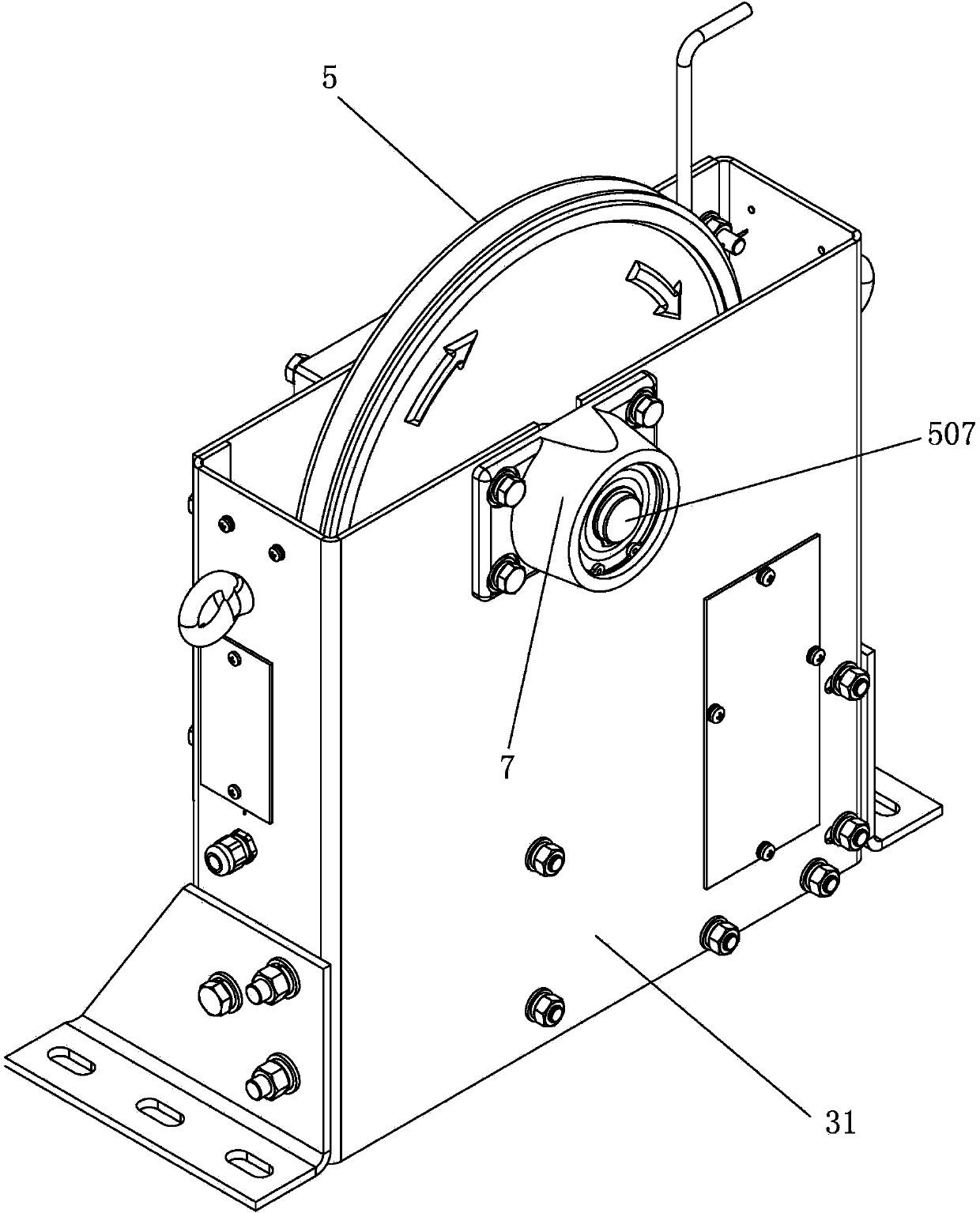
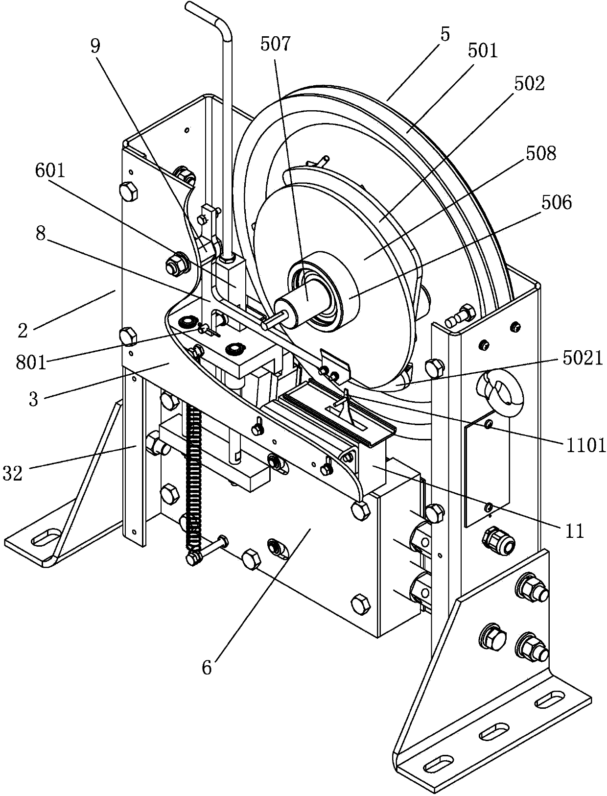
[0035] Such as Figure 1 to Figure 3 As shown, the speed governor of a high-speed elevator of the present invention includes a corner plate 1, a box-shaped support 2, the corner plate 1 is fixed on the ground, the box-shaped support 2 is fixed on the corner plate 1, and the box-shaped support 2 includes a front side plate 3, a rear Side plate 31, left side plate 32, right side plate. A sheave part 5 is provided in the box-shaped support 2, and the sheave part 5 includes a sheave 501 arranged vertically, a steel wire rope (not shown in the figure) is wound on the sheave 501, and a main shaft 507 arranged horizontally passes through it vertically from front to back. Through the front side plate 3, the sheave 501, and the rear side plate 31, wherein the main shaft 507 and the sheave 501 are interference fit. The front end and the rear end of the main shaft 507 are all positioned outside the box-shaped support 2. The front end of the main shaft 507 is provided with a front bearin...


PUM


Abstract

The invention relates to a speed limiting device for a car or a cage or a bucket, in particular to a high-speed elevator speed limiter. The high-speed elevator speed limiter comprises a rope wheel, a steel wire rope is wound on the rope wheel, two small shafts are arranged on the rope wheel, the two small shafts are rotatably hinged to special-shaped throwing pieces respectively, connecting rods are connected between the two throwing pieces, a quadrilateral structure is formed by the throwing pieces and the connecting rods, the movable ends of the throwing pieces are fixedly connected with springs, a switch component is arranged below the throwing pieces, the switch component can be knocked out in the centrifugal motion process of the throwing pieces, and an elevator is made to be switched off. The high-speed elevator speed limiter is easy and convenient to operate, accurate in motion speed, capable of fast braking the elevator, good in speed limiting effect, low in use and maintenance effect and high in safety factor.

Description

technical field [0001] The invention relates to the application technical field of detection, fault correction or safety devices in elevators, in particular to a speed limiting device for a car, a cage or a skip. Background technique [0002] The elevator speed limiter is one of the safety control components in the elevator safety protection system. It monitors and controls the speed of the car at any time. When the car is overspeeded for any reason during the operation of the elevator, that is, when it reaches 115% of the rated speed of the elevator, or even falls, it can send a switch signal in time to cut off the speed of the car. The power supply circuit makes the traction machine brake. If the elevator still cannot brake and the speed continues to increase, the speed limiter will drive the safety gear installed at the bottom of the car to stop the car forcibly, thus avoiding casualties and equipment damage accidents. [0003] Currently domestically produced high-speed...

Claims


Application Information

Patent Timeline
Patent Type & Authority Applications(China)
IPC IPC(8): B66B5/06B66B5/24
Inventor 海立冬贾砚华周军然孙雪松王晓会
Owner HEBEI DONGFANG FUDA MACHINERY
Why Eureka
Try Eureka