cnc processing machine

A processing machine and workbench technology, applied in the field of CNC machine tools, can solve the problems of inability to divide and process multiple workpieces at the same time, cost, and poor efficiency

Active Publication Date: 2016-11-30
山东火炬科技服务有限公司
View PDF5 Cites 0 Cited by
  • Summary
  • Abstract
  • Description
  • Claims
  • Application Information

AI Technical Summary

Problems solved by technology

[0002] CNC processing machine is the abbreviation of computer numerical control machine tool (Computernumericalcontrol). It is an automatic machine tool controlled by a program. It decodes, and tells the Cartesian position coordinates of the machining tool of the CNC machine tool, controls the feed speed of the tool and the spindle speed, so that the machine tool can complete cutting, drilling and other operations on the workpiece. Compared with manual processing, CNC machining has more advantages. The advantage is that the parts produced by its processing are accurate and repeatable; however, the CNC processing machines in the prior art usually only have one processing station, and cannot divide and process multiple workpieces at the same time, resulting in poor efficiency and long processing time. Long; and in the process of batch processing, each processing program needs to transport the workpiece to the processing station, resulting in time-consuming and cost-increasing; the Chinese patent announcement number is CN202377909U, which discloses a CNC multi-axis processing machine , including two rails, two moving tables, one cutting device and two sets of drilling devices. Although it can solve the problem of processing workpieces at the same time, the loading and unloading process of workpieces still needs to be done manually, and the labor intensity is still relatively high. , the degree of automation is not high

Method used


Image

  • cnc processing machine
  • cnc processing machine

Examples


Embodiment Construction

[0022] The specific implementation manners of the present invention will be further described in detail below in conjunction with the accompanying drawings and embodiments. The following examples are used to illustrate the present invention, but are not intended to limit the scope of the present invention.

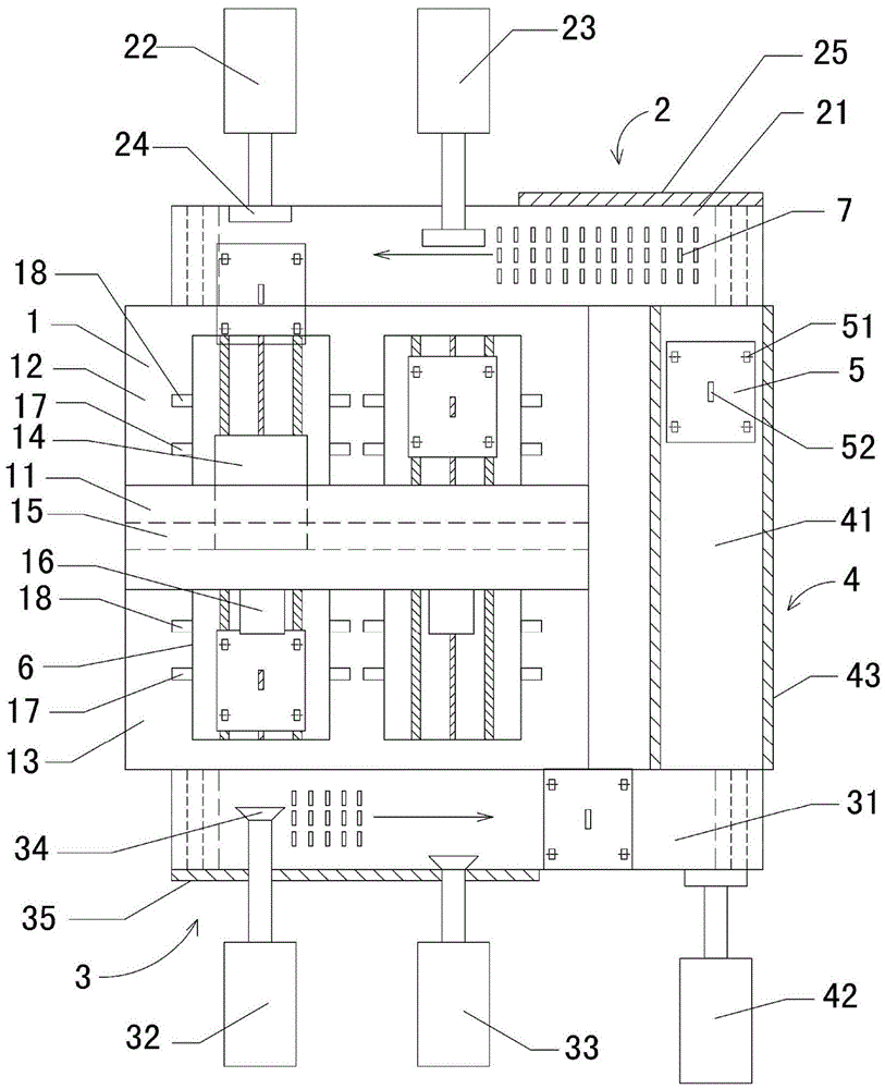
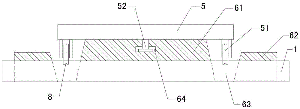
[0023] see figure 1 and figure 2 As shown, a CNC processing machine includes a workbench 1, a feeding mechanism 2, a discharge mechanism 3, a circular feeding mechanism 4 and a mobile table 5, wherein: the middle part of the workbench 1 is provided with a seat body 11, and the seat body 11 will The front end and the rear end of the workbench are divided into a material feeding area 12 and a material discharging area 13, the middle part of the seat body 11 is provided with an opening, and two guide rail seats 6 are arranged side by side on the top surface of the workbench in the opening, and the seat body 11 One side of the feeding area is provided with a cutting device ...


PUM


Abstract

The invention relates to an automatic loading and unloading process which can effectively complete the process of processing multiple workpieces at the same time. It includes a workbench, a feeding mechanism, a discharging mechanism, a circular feeding mechanism and a mobile table. The feeding mechanism includes a feeding conveyor belt, a first feeding cylinder and a second feeding cylinder. The first feeding cylinder and the second feeding cylinder are used to automatically move the mobile platform The feeding conveyor belt is pushed to the guide rail seat, and is also used to push the mobile table from the side of the feeding area of ​​the guide rail seat to the side of the discharging area; the discharging mechanism includes the discharging conveyor belt, the first discharging oil cylinder and the second discharging Oil cylinder, the output ends of the first discharge cylinder and the second discharge cylinder are provided with suction cups, the first discharge cylinder and the second discharge cylinder are used to attract the mobile platform from the guide rail seat to the discharge conveyor belt, and the discharge conveyor belt uploads A discharge reduction motor is dynamically connected; the circular feeding mechanism includes a slideway and a pusher cylinder, and the two ends of the slide are respectively connected with the discharge end of the discharge conveyor belt and the feed end of the feed conveyor belt.

Description

technical field [0001] The invention relates to a numerically controlled machine tool, in particular to a CNC processing machine. Background technique [0002] CNC processing machine is the abbreviation of computer numerical control machine tool (Computernumericalcontrol). It is an automatic machine tool controlled by a program. It decodes, and tells the Cartesian position coordinates of the machining tool of the CNC machine tool, controls the feed speed of the tool and the spindle speed, so that the machine tool can complete cutting, drilling and other operations on the workpiece. Compared with manual processing, CNC machining has more advantages. The advantage is that the parts produced by its processing are accurate and repeatable; however, the CNC processing machines in the prior art usually only have one processing station, and cannot divide and process multiple workpieces at the same time, resulting in poor efficiency and long processing time. Long; and in the process...

Claims


Application Information

Patent Timeline
Patent Type & Authority Patents(China)
IPC IPC(8): B23P23/02B23Q7/00
Inventor 钱仁元
Owner 山东火炬科技服务有限公司
Why Eureka
Try Eureka