A hydraulic locking power tool table for compound machining
A technology of compound machining and driven tool holder, which is applied in metal processing equipment, metal processing mechanical parts, tool holders, etc., can solve the problems of complex structure and high cost of the driven tool holder, and achieve the effect of simple structure, complete functions and simple installation.
- Summary
- Abstract
- Description
- Claims
- Application Information
AI Technical Summary
Problems solved by technology
Method used
Image
Examples
Embodiment Construction
[0022] Specific embodiments of the present invention will be described in detail below in conjunction with the accompanying drawings.
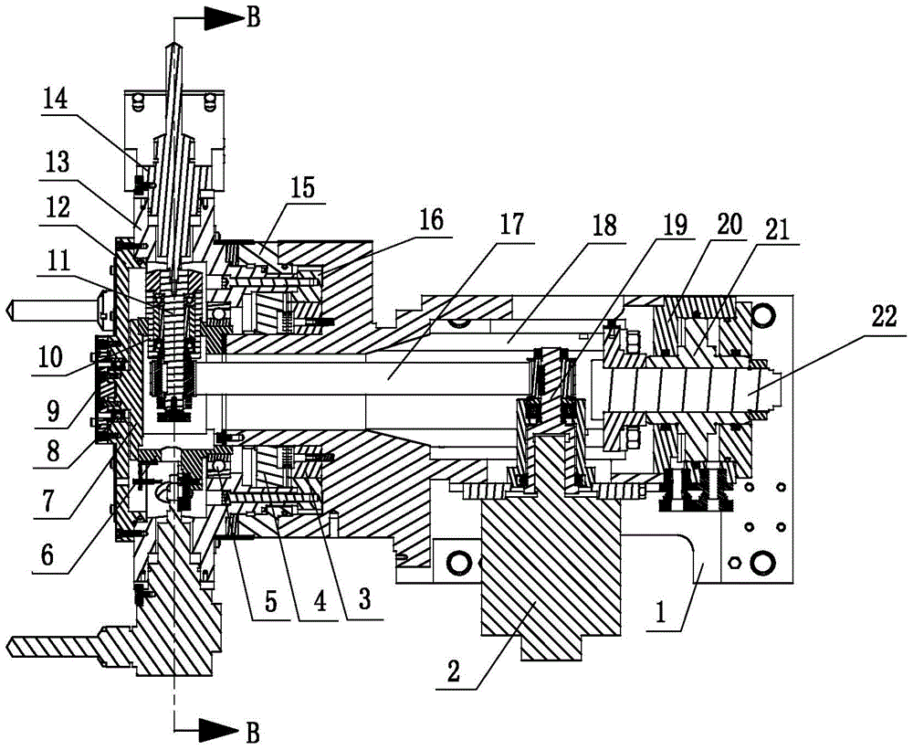
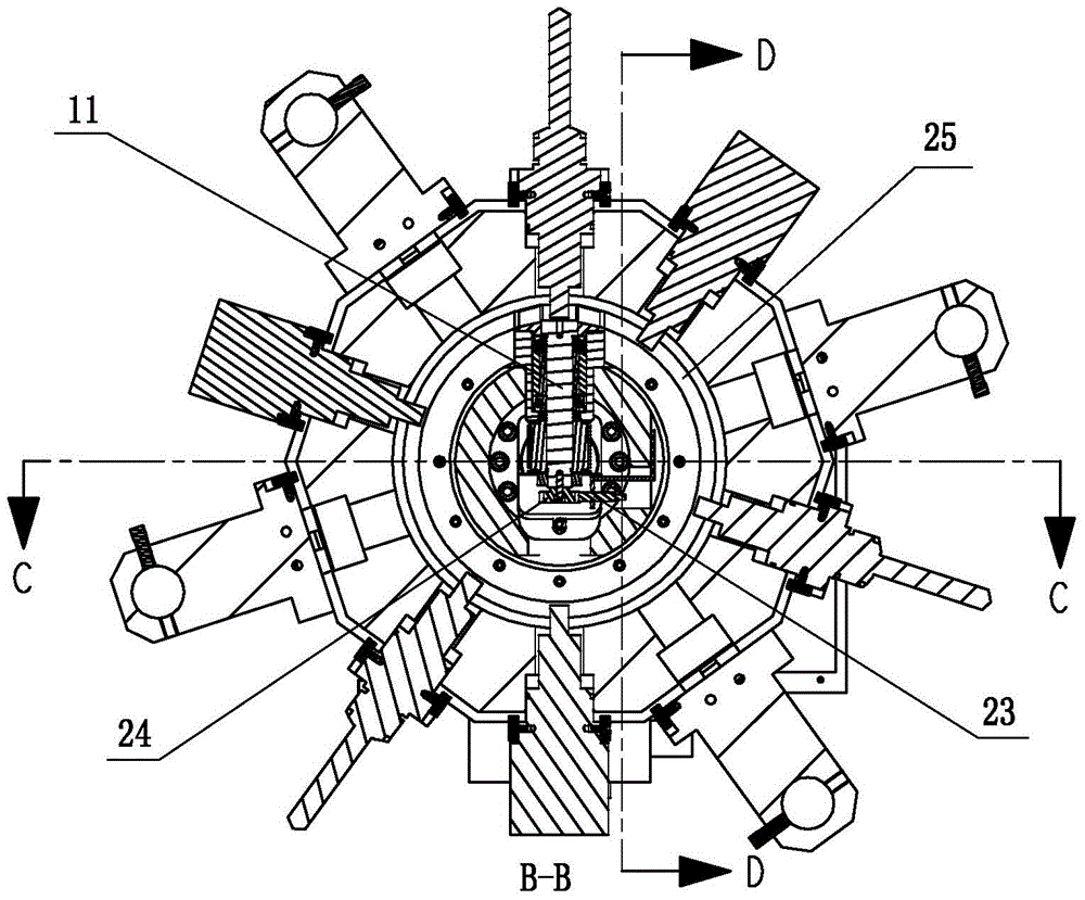
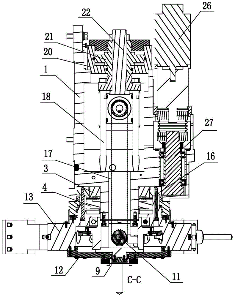
[0023] Such as Figure 1 ~ Figure 4 As shown, the present invention includes a tool holder 1 , a hollow cutter head 13 , a power drive mechanism, a tool change drive mechanism, a cutter head locking mechanism and a plurality of driven tool holders 14 . The driven knife seat 14 is installed on the cutter head 13, and a plurality of driven knife seats are distributed at intervals along the circumferential direction on the cutter head; Groove, the annular groove is peripheral to the transmission cavity, and the power drive mechanism includes a power drive motor 2, a driving shaft 19, a driven shaft 11, a hollow flange seat 6, a flange seat end cover 7 and a slave The driving shaft angle sensing mechanism, the flange seat 6 includes a hollow flange and a bearing seat sleeve 10 installed on the flange, a driven shaft hole is arranged in the bearin...
PUM
 Abstract
Description
Claims
Application Information
 - R&D
- Intellectual Property
- Life Sciences
- Materials
- Tech Scout
- Unparalleled Data Quality
- Higher Quality Content
- 60% Fewer Hallucinations
Browse by: Latest US Patents, China's latest patents, Technical Efficacy Thesaurus, Application Domain, Technology Topic, Popular Technical Reports.
© 2025 PatSnap. All rights reserved.Legal|Privacy policy|Modern Slavery Act Transparency Statement|Sitemap|About US| Contact US: help@patsnap.com


