
A Blind Interference Alignment Method for SISO Systems

A technology of blind interference and equations, which is applied in baseband system components, diversity/multi-antenna systems, transmission control/equalization, etc., can solve problems such as high complexity and inability to achieve blind interference alignment in SISO systems, and increase signal space Dimensions, solving single-antenna constraint problems, and improving throughput

Inactive Publication Date: 2017-12-19
UNIV OF ELECTRONIC SCI & TECH OF CHINA
View PDF4 Cites 0 Cited by
  • Summary
  • Abstract
  • Description
  • Claims
  • Application Information

AI Technical Summary

Problems solved by technology

To weaken its limitation, Tiangao Gou, Chenwei Wang, and Syed A.Jafar., Aiming Perfectly in the Dark-Blind Interference AlignmentThrough Staggered Antenna Switching, IEEE Trans.Sinal Processing, Vol.59, NO.6, June2011, pp.2734- 2744.Qing F.Zhou,Q.T.Zhang On Blind Interference Alignmentover Homogeneous Block Fading Channels,IEEE Communications Letters,Vol.16,NO.9,September2012,pp.1432-1435, has been mentioned in the literature to achieve blind interference alignment, but in When using the above blind interference alignment, the receiving end needs to adopt some special forms to achieve interference alignment by traversing all modes and switching, which is complex and cannot achieve blind interference alignment in the SISO system

Method used


Image

  • A Blind Interference Alignment Method for SISO Systems
  • A Blind Interference Alignment Method for SISO Systems
  • A Blind Interference Alignment Method for SISO Systems

Examples


Embodiment Construction

[0016] The technical solution of the present invention will be described in detail below in combination with the embodiments and the accompanying drawings.

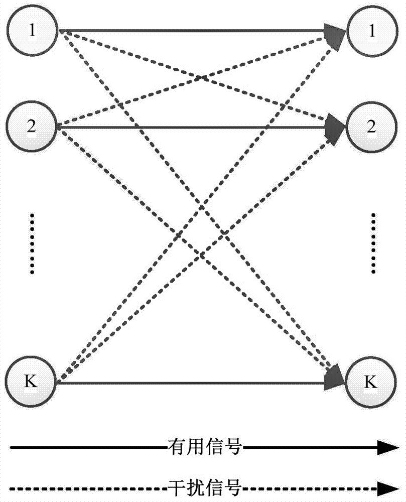
[0017] In the present invention, the transmitted data is a complex signal. The transmitted data flows through the design of asymmetric complex signals, and the channel model can be considered as a virtual multi-antenna system to solve the single-antenna constraint problem. Let the receiving signal of the target user i at the receiving end be expressed as:

[0018]

[0019] To ensure an interference-aligned signal space, with an asymmetric complex signal design, the signal can be rewritten as:

[0020]

[0021] where: y i =[Re{y i} Im{y i}] T , x i =[Re{x i} Im{x i}] T , n i =[Re{n i} Im{n i}] T , () T represents the transpose of a vector, x i Indicates the signal sent by user i. Re{} represents the real part of the complex signal, and Im{} represents the imaginary part of the complex signal. The cha...


PUM


Abstract

The invention discloses a blind interference alignment method of an interference channel in a SISO system. Firstly, the design of asymmetric complex signal is used to increase the dimension of the signal space, effectively solving the single antenna constraint problem, and then the receiving end uses the channel information and precoding vector information to design a filter to completely eliminate interference, and proves that the design of the transmitting end The precoding vector does not need to know the channel information, so as to realize the blind interference alignment. In addition, the invention proves that the system degree of freedom of K users interfering with the channel reaches K / 2, which is also the upper limit of the system degree of freedom when the channel state information of the transmitting end is known. The blind interference alignment method proposed by the present invention can effectively solve the problem that the signal space dimension is not high enough and the perfect channel state information is difficult to obtain in an actual system, effectively eliminate system interference, and improve throughput.

Description

technical field [0001] The invention belongs to the technical field of mobile communication, and in particular relates to a method which can effectively improve the interference network capacity and completely eliminate the interference. Background technique [0002] With the rapid development of wireless communication, the number of end users of wireless network has increased sharply, and the main factors affecting communication quality are interference and system capacity problems. In a wireless communication system, useful signals are affected by interference during propagation, which degrades the communication quality of the system. In order to improve system capacity, interference elimination or interference suppression has become a very important research topic. [0003] Interference Alignment (IA) technology can effectively increase the capacity of the interference network and improve the throughput limitation of wired and wireless networks in the traditional way. It...

Claims


Application Information

Patent Timeline
IPC IPC(8): H04L25/03H04L25/02H04B7/02H04B7/005
Inventor 李强王平吴彩凤
Owner UNIV OF ELECTRONIC SCI & TECH OF CHINA
Learn More