
Sound source locating method based on improved PHAT weighting time delay estimation and implementation system thereof

A technology for time delay estimation and sound source localization, which is used in positioning, radio wave measurement systems, instruments, etc., and can solve problems such as inability to accurately identify multiple sound sources and inability to distinguish directional noise.

Active Publication Date: 2014-12-03
SHANDONG UNIV
View PDF3 Cites 34 Cited by
  • Summary
  • Abstract
  • Description
  • Claims
  • Application Information

AI Technical Summary

Problems solved by technology

Due to the error brought by the basic model, it cannot accurately identify multiple sound sources, nor can it distinguish directional noise. It is only suitable for time delay estimation of strong signals, so the generalized cross-correlation function method is not suitable for relatively Large reverberation and associated noise occasions

Method used


Image

  • Sound source locating method based on improved PHAT weighting time delay estimation and implementation system thereof
  • Sound source locating method based on improved PHAT weighting time delay estimation and implementation system thereof
  • Sound source locating method based on improved PHAT weighting time delay estimation and implementation system thereof

Examples


Embodiment 1

[0070] A sound source localization method based on improved PHAT weighted delay estimation, specifically comprising the following steps:

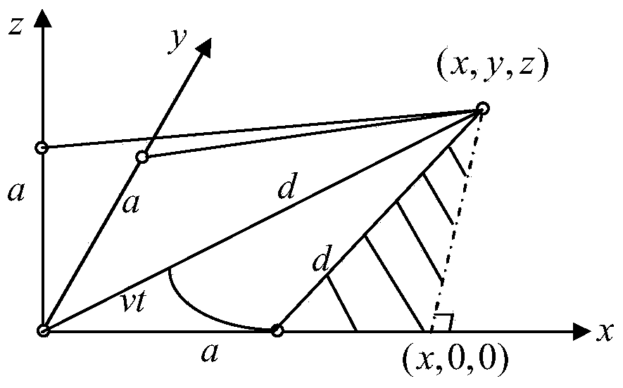
[0071] (1) Select (0,0,0), (a,0,0), (0,a,0), (0,0,a) four positions to place the microphone in the three-dimensional Cartesian coordinate system, and get the microphone array, the a is a fixed parameter, and the a represents three microphones located at the coordinates (a,0,0), (0,a,0), and (0,0,a) respectively to the origin coordinates (0 ,0,0) the distance of the microphone at the position;

[0072] (2) The microphone array in step (1) collects 4-way sound signals, and amplifies the sound signals, and realizes the DC pad processing for the amplified sound signals, and outputs an analog signal;

[0073] The described DC boosting process is realized by utilizing the existing MIC and voltage amplification boosting circuit, and the MIC and voltage amplification boosting circuit includes 4 microphones and two-stage operational amplifiers to r...

Embodiment 2

[0083] According to a sound source localization method based on improved PHAT weighted time delay estimation described in Embodiment 1, the difference is that the time delay estimation algorithm is performed using the improved PHAT weighted generalized cross-correlation function method described in step (5). Processing, specifically including the following steps:

[0084] a. The 4 digital signals described in step (4) are respectively set to x 1 (n), x 2 (n), x 3 (n), x 4 (n), the 4 digital signals described in step (4) are sequentially subjected to windowing filter processing and Fourier transform to obtain frequency domain signal X successively 1 (k), X 2 (k), X 3 (k), X 4 (k), said n and k are both integers, representing the serial numbers of points in said digital signal;

[0085] b. Using the improved PHAT weighted generalized cross-correlation function method to calculate X in the 4 channels of frequency domain signals obtained in step a through formula Ⅰ, formula...

Embodiment 3

[0120] According to the sound source localization method based on the improved PHAT weighted delay estimation described in Embodiment 2, the difference is that the value of N is 0.8.


PUM


Abstract

The invention relates to a sound source locating method based on improved PHAT weighting time delay estimation. The sound source locating method comprises the steps that a microphone array collects four paths of sound signals, the sound signals are converted into digital signals through an A / D sampling circuit, time delay estimation algorithm processing is conducted through an improved PHAT weighting generalized cross correlation function method, a time delay estimation value is obtained, a nonlinear equation system is solved through the iteration method according to the time delay estimation value and the spatial position of the microphone array, and then the relative position of a sound source is obtained. According to the sound source locating method based on improved PHAT weighting time delay estimation, the arrangement of the microphone array is similar to the arrangement of the origin of a rectangular coordinate system and fixed length points on the x-axis, the y-axis and the z-axis; the calculated quantity is small, the device requirement is low, the speed is high, and instant locating is achieved; a sound source locating system is applied to social life, the military field and other aspects such as a video session, path planning and locating of a sniper.

Description

technical field [0001] The invention relates to a sound source localization method based on improved PHAT weighted time delay estimation and an implementation system thereof, belonging to the technical field of sound source localization. Background technique [0002] Sound is an important way to obtain information about external things. Sound can not only carry voice information, but based on the characteristics of sound propagation and its path itself, we can also obtain location information other than the content information carried by sound through sound source positioning technology. And it can be applied to related fields such as tracking search and route planning to improve the working efficiency of some systems. [0003] The previous positioning methods mainly relied on radio, laser, sonar and other equipment. By actively sending signals and listening to the waves reflected by the measured object, the received reflected waves were analyzed and calculated to obtain the...

Claims


Application Information

Patent Timeline
Patent Type & Authority Applications(China)
IPC IPC(8): G01S5/22
CPCG01S5/22
Inventor 王永倪暹王照君王雪峰
Owner SHANDONG UNIV
Learn More