
Equipment for scanning facial porosity of rock and method thereof

A technology of surface porosity and equipment, which is applied in the field of oil drilling, can solve the problems of large measurement error of rock surface porosity and failure to obtain rocks, etc., and achieve the effect of simple operation and accurate measurement

Inactive Publication Date: 2014-12-03
CHINA PETROLEUM & CHEM CORP +1
View PDF6 Cites 11 Cited by
  • Summary
  • Abstract
  • Description
  • Claims
  • Application Information

AI Technical Summary

Problems solved by technology

[0004] The purpose of the present invention is to solve the problems that the existing rock surface porosity measurement error is large and the real pore-throat characteristic parameters in the rock cannot be obtained

Method used


Image

  • Equipment for scanning facial porosity of rock and method thereof
  • Equipment for scanning facial porosity of rock and method thereof

Examples


Embodiment Construction

[0023] Hereinafter, the present invention will be described in detail with reference to the accompanying drawings.

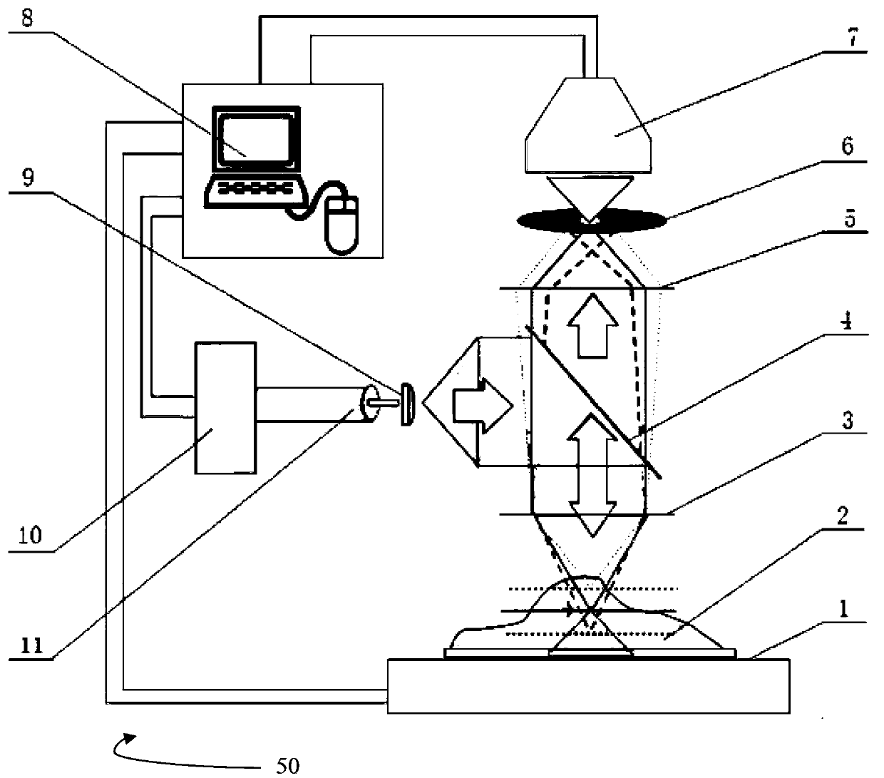
[0024] figure 1 A device 50 for scanning rock face porosity according to the invention is schematically shown.

[0025] The device 50 includes a stage 1 for placing a rock sample 2, and the stage 1 can move up and down slightly in the vertical direction. This can be achieved by providing a micro-motion mechanism for the stage 1 .

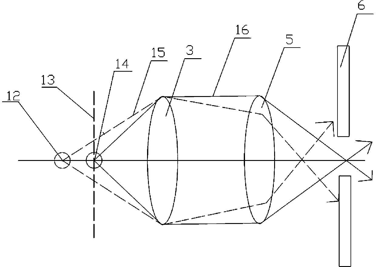
[0026] refer to figure 1 , an objective lens 3 , a polarizer 4 and a focusing lens 5 are arranged above the stage 1 from bottom to top. For observation, the focal point of the objective lens 3 is inside the rock sample 2, and the focal plane of the objective lens 3 is the section to be observed.

[0027] The fluorescence incident hole plate 6 is installed above the focusing lens 5 at a certain distance. The focal point of the focusing lens 5 is located in the light transmission hole of the fluorescence incident hole plate 6 .

...


PUM


Abstract

The invention puts forward equipment for scanning facial porosity of rock and belongs to the field of chronology. Pores of rock are filled with a fluorescent material. The equipment comprises an object stage, an objective lens, a polariscope, a focusing lens, a laser scanning unit, a fluorescence incident pore-plate, a photoelectric signal amplifier and a control processing unit. The object stage can move up and down along the vertical direction. The objective lens, the polariscope and the focusing lens are successively arranged from bottom to top above the object stage. The laser scanning unit is arranged at one side of the polariscope and can move. The fluorescence incident pore-plate and the photoelectric signal amplifier are successively arranged from bottom to top above the focusing lens. The photoelectric signal amplifier can receive a fluorescence signal from a laser-activated fluorescent material and convert the fluorescence signal to an electrical signal. The control processing unit can control up-down movement of the object stage, control operation of the laser scanning unit and receive and process the electrical signal from the photoelectric signal amplifier. The invention also puts forward a corresponding method. According to the equipment and the method, facial porosity of rock can be observed accurately and conveniently.

Description

technical field [0001] The invention relates to a device for scanning the porosity of rock surfaces, which belongs to the field of petroleum drilling. The invention also relates to a method for scanning the porosity of a rock face. Background technique [0002] In the prior art, when testing the rock surface porosity, the rock thin section is usually observed with an ordinary optical microscope, and then the area of ​​the pores is determined within the demarcated area by means of ordinary camera imaging or observation with the naked eye, and then the observed rock is obtained through calculation. Such face rate. [0003] The results obtained by this method are affected by instruments and people, and the error is large; at the same time, the determination of the pore-throat characteristic parameters in the rock reservoir can only be carried out by indirect measurement, and the real pore-throat characteristic parameters in the rock cannot be obtained. Contents of the invent...

Claims


Application Information

Patent Timeline
IPC IPC(8): G01N15/08
Inventor 康志江李彤赵艳艳张允崔书岳
Owner CHINA PETROLEUM & CHEM CORP
Learn More