An installation method of a sintering machine dust removal system

A technology of dust removal system and installation method, which is applied in the direction of furnace type, furnace, lighting and heating equipment, etc., which can solve the problems of difficult installation quality assurance, long installation time, and many installation hidden dangers, and achieve easy lifting and counterpart connection, and work The effect of reducing the amount and reducing the labor operation

Active Publication Date: 2015-12-30
TIANJIN 20 CONSTR
View PDF6 Cites 2 Cited by
  • Summary
  • Abstract
  • Description
  • Claims
  • Application Information

AI Technical Summary

Problems solved by technology

[0022] (1) The installation time is long; (2) The installation cost is high; (3) The installation quality is not easy to guarantee; (4) There are many hidden dangers in the installation

Method used


Image

  • An installation method of a sintering machine dust removal system
  • An installation method of a sintering machine dust removal system
  • An installation method of a sintering machine dust removal system

Examples


Embodiment Construction

[0056] In order to make the technical solution of the present invention more clearly understood, it will be described in detail below in conjunction with the accompanying drawings and embodiments.

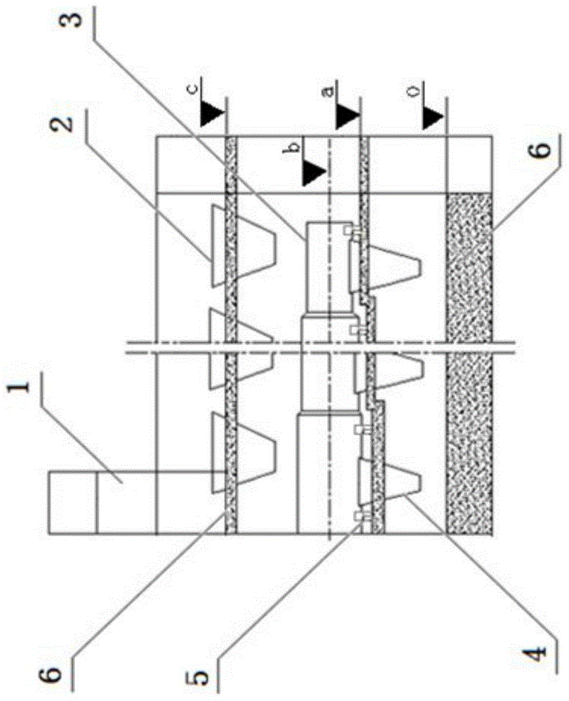
[0057] The installation method of the dust removal system of the sintering machine of the present invention is carried out by adopting a self-made gantry type electric suspension vehicle and a bracket type electric vehicle.

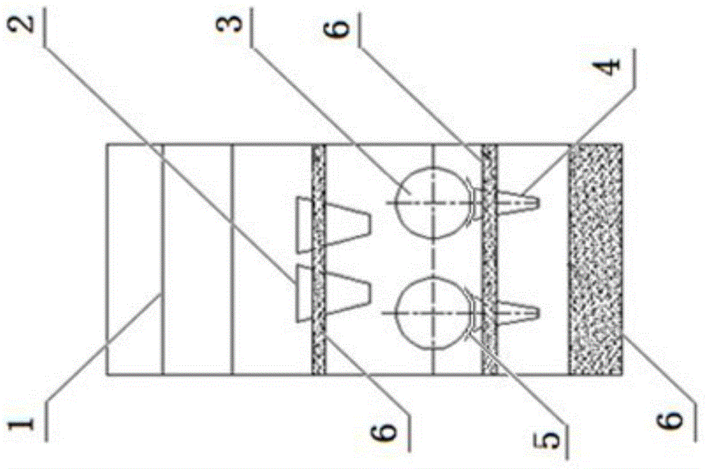
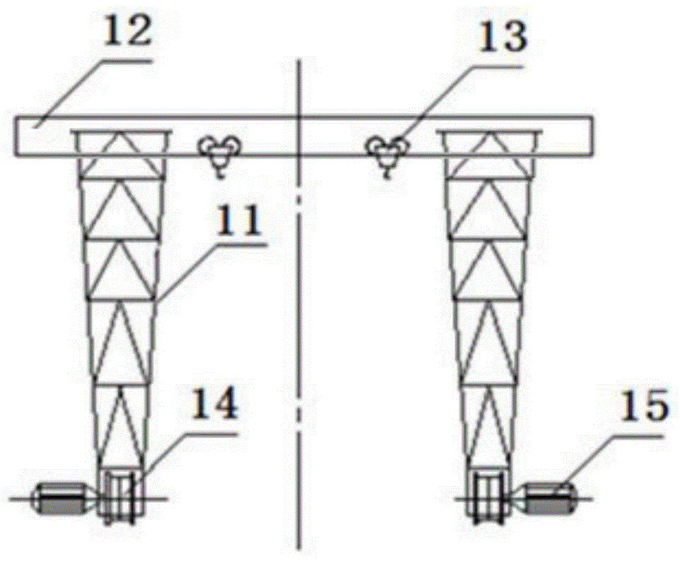
[0058] refer to image 3 , Figure 4 , the gantry type electric suspension vehicle includes two vehicle frames 11 made of angle steel, H-shaped steel or steel plate; the upper ends of the two vehicle frames 11 are provided with vehicle beams 12, and the vehicle beams 12 are laid The steel plates on both sides of the width of the upper end of the vehicle frame 11 are composed of steel plates welded between the two steel plates. The slideway and the two cat head cranes 13 installed thereon constitute a sliding movement pair; two sides of the bottom end of the ...


PUM


Abstract

The invention discloses a mounting method for a dedusting system of a sintering machine. The mounting method comprises the following steps: surveying and setting out on a cement concrete beam of a workshop with the elevation a to determine the spacial position of a central line of a dedusting pipeline and the elevation b; assembling a steel platform, with the elevation a on the upper surface, on the machine head side of the workshop; paving a temporary track that is used for a gantry-type electric suspending vehicle and stretches to the steel platform, and manufacturing the gantry-type electric suspending vehicle; paving a temporary track that is used for a bracket-type electric vehicle and stretches out of the workshop; lifting and mounting a pipeline bracket and all components of the dedusting pipeline; mounting all little hoppers on a cement concrete beam, with the elevation c, of the workshop; paving and welding a walking board inside the dedusting pipeline; modifying the gantry-type electric suspending vehicle into the bracket-type electric vehicle; lifting and mounting all ash collecting hoppers; performing other steps. The mounting method has the advantages that a plurality of defects in the prior art are overcome, the mounting period is shortened, the mounting cost is reduced, the relatively high mounting quality is guaranteed, and the mounting process has reliable security.

Description

technical field [0001] The invention relates to an installation method of a sintering machine, more specifically, the invention relates to an installation method of a dust removal system of a sintering machine. Background technique [0002] Generally, the sintering machine is installed in a multi-storey factory building and installed in a bottom-up order. In the whole process of installing the sintering machine, the most critical process is the installation of the dust removal system. [0003] figure 1 , figure 2 The situation of the constituent units of the dust removal system of the sintering machine is shown respectively, the constituent units include the small grid funnel 2 installed on the upper cement concrete beam 6 in the sintering machine workshop, and the small grid funnel 2 installed on the middle cement concrete beam 6 through the pipe support 5 The dust removal pipeline 3 and the dust collection bucket 4 installed below the dust removal pipeline 3, the conve...

Claims


Application Information

Patent Timeline
Patent Type & Authority Patents(China)
IPC IPC(8): F27B21/08
Inventor 王彩东
Owner TIANJIN 20 CONSTR
Why Eureka
Try Eureka