Novel brake valve device

A brake valve, a new type of technology, applied in the direction of brakes, brake components, control valves and air release valves, etc., can solve the problem of gas circulation, anti-pressure injection, expansion, guidance, and uniform output. The working process is uneven and upward. The air supply of the gas storage valve and the lower gas storage valve is not synchronized, and the maintenance or maintenance of the brake valve is difficult, so as to achieve the effect of light braking process, easy maintenance or maintenance, and reduction of impact force

Active Publication Date: 2014-12-03
谢洪川
View PDF7 Cites 0 Cited by
  • Summary
  • Abstract
  • Description
  • Claims
  • Application Information

AI Technical Summary

Problems solved by technology

[0006] The purpose of the present invention is to provide a new type of brake valve device, which solves the difficulty of repairing or maintaining the existing brake valve, and performs reverse pressure injection, expansion, guidance, and uniform output of the gas circulation. The air supply volume of the upper air storage valve and the lower air storage valve is not synchronized and inconsistent, which solves a series of problems in the braking process

Method used


Image

  • Novel brake valve device
  • Novel brake valve device
  • Novel brake valve device

Examples


Embodiment

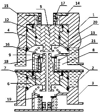
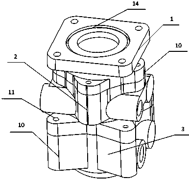
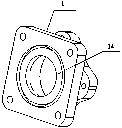
[0040] Such as Figure 1 to Figure 12 As shown, a new type of brake valve device, including three sequentially connected and mutually detachable upper cavity valve body 1, middle cavity valve body 2, lower cavity valve body 3, sleeved in the first valve body in the lower end of the upper cavity valve body The piston casing 4 is slidably connected to the first piston 5 in the first piston casing, and the ejector rod seat 17 connected to the upper end of the first piston is sleeved to the second piston casing 6 in the lower end of the middle chamber valve body, and is slidably connected to the second piston casing 6. The second piston 7 in the two-piston outer casing, the upper gas storage valve 18 connected to the upper end of the second piston, and the lower gas storage valve 19 installed in the valve body of the lower chamber, the lower end of the first piston is movably connected with the upper gas storage valve , the lower end of the second piston is movably connected with ...


PUM


Abstract

The invention discloses a novel brake valve device. The novel brake valve device comprises an upper cavity valve body, a middle cavity valve body and a lower cavity valve body. The upper cavity valve body, the middle cavity valve body and the lower cavity valve body are connected in sequence, are detachable and are fixed with a connecting base. A first piston sleeve and a second piston sleeve are detachable. The lengths of the inner walls of the first piston sleeve and the second piston sleeve are smaller than the lengths of the outer walls of the first piston sleeve and the second piston sleeve, inward-concave arc faces are formed at the lower ends of the first piston sleeve and the second piston sleeve, and space data of the two arc faces are equal. The top of the first section of a second piston is provided with a connecting rod used for being movably connected with the bottom of a first piston. The novel brake valve device is of a detachable structure and is convenient to install, maintain and repair, the valve bodies are stably installed, airflow is uniform, stress force in a cavity is uniform, upper brake and lower brake are synchronous and uniform, and airflow resistance, confusion and nonuniformity caused by airflow right-angle impact on the market are avoided, so that the baking process is light, gentle, flexible, sensitive, uniform and stable, upper loop brake and lower loop brake are synchronous and uniform, and the novel brake valve device has the high practical value and is particularly suitable for large-scale usage and popularization.

Description

technical field [0001] The invention relates to a brake valve device, in particular to a novel brake valve device, belonging to the field of automobile brakes. Background technique [0002] The brake valve is the main control device in the vehicle braking system. It realizes sensitive follow-up control during the braking process and release process of the dual-circuit main braking system. The brake valve is mainly composed of the upper cavity piston, the lower cavity piston, Composed of push rod, balance spring, return spring (upper and lower chambers), upper chamber valve, lower chamber valve, air inlet, air outlet, exhaust port, and vent hole. When the driver steps on the pedal, the piston presses down the balance spring by stretching the pull rod, and the piston moves down. First, the exhaust valve is closed and the intake valve is opened. The air chamber pushes the diaphragm of the air chamber to rotate the brake cam to achieve wheel braking. [0003] In the existing ...

Claims


Application Information

Patent Timeline
Patent Type & Authority Applications(China)
IPC IPC(8): B60T15/02
Inventor 谢洪川
Owner 谢洪川
Why Eureka
Try Eureka