
In-mold embedded type optical fiber

An embedded, optical fiber technology, applied in the coating and other directions, can solve the problems of non-conductive molds, easy fatigue of employees, shortened mold life, etc., and achieve the effect of reducing the number of unloading and mold repairs, low manufacturing costs, and quality improvement.

Active Publication Date: 2014-12-03
KENTA ELECTRONIC MFG KUNSHAN CO LTD
View PDF4 Cites 4 Cited by
  • Summary
  • Abstract
  • Description
  • Claims
  • Application Information

AI Technical Summary

Problems solved by technology

[0002] In-mold embedded molding technology has been widely used in the plastic manufacturing industry. The embedded molding is mainly used for plastic products with hardware. The principle is to put the hardware into the mold when injection molding In the cavity, the mold is then closed for injection molding. If the hardware is missing or misplaced during the mold closing process, the hardware parts of the product will become colloid and will not be able to conduct electricity, or the mold will be crushed and cannot be produced.
At present, during embedded molding, the hardware is mainly inspected manually. During mass production and long-term production, the employees are prone to fatigue, and it is easy to miss the placement or the hardware is not put in place, resulting in glue entering the cavity or pressing the mold, making the mold Reduced lifespan and reduced productivity

Method used


Image

  • In-mold embedded type optical fiber

Examples


Embodiment Construction

[0010] The preferred embodiments of the present invention will be described in detail below in conjunction with the accompanying drawings, so that the advantages and features of the present invention can be more easily understood by those skilled in the art, so as to define the protection scope of the present invention more clearly.

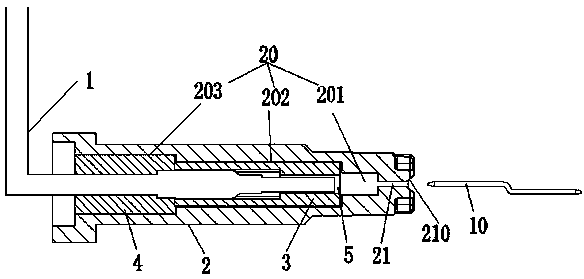
[0011] see figure 1 , the embodiment of the present invention includes: an in-mold embedded optical fiber, including: an optical fiber 1 and a mold body 2, and a stepped hole 20 and a through hole 21 for placing a hardware 10 are provided inside the mold body 2. The stepped hole 20 includes a first stepped hole 201, a second stepped hole 202 and a third stepped hole 203, the fiber guide block 3 is placed in the second stepped hole 202, and the optical fiber fixing block 3 is placed in the third stepped hole 203 Block 4, the middle part of the optical fiber guide block 3 and the optical fiber fixing block 4 is respectively provided with an inserti...


PUM


Abstract

The invention discloses an in-mold embedded type optical fiber. The in-mold embedded type optical fiber comprises an optical fiber and a mold body, wherein the mold body is internally provided with a stepped hole and a through hole for holding hardware; the stepped hole comprises a first stepped hole, a second stepped hole and a third stepped hole; an optical-fiber guiding block is held in the second stepped hole; an optical-fiber fixing block is held in the third stepped hole; the middle parts of the optical-fiber guiding block and the optical-fiber fixing block are respectively and horizontally provided with an inserted hole; the optical fiber is held in the inserted holes of the optical-fiber fixing block and the optical-fiber guiding block; and the other end of the optical fiber extends to the outer part of the mold body. By the mode, the in-mold embedded type optical fiber disclosed by the invention has the advantages that the service life of a mold can be prolonged, and the production efficiency is also improved.

Description

technical field [0001] The invention relates to the technical field of mechanical manufacturing, in particular to an in-mold embedded optical fiber. Background technique [0002] In-mold embedded molding technology has been widely used in the plastic manufacturing industry. The embedded molding is mainly used for plastic products with hardware. The principle is to put the hardware into the mold when injection molding In the cavity, the mold is then closed for injection molding. If the hardware is missing or misaligned during the mold closing process, the hardware parts of the product will become colloidal and cannot conduct electricity, or the mold will be crushed and cannot be produced. At present, during embedded molding, the hardware is mainly inspected manually. During mass production and long-term production, the employees are prone to fatigue, and it is easy to miss the placement or the hardware is not put in place, resulting in glue entering the cavity or pressing th...

Claims


Application Information

Patent Timeline
Patent Type & Authority Applications(China)
IPC IPC(8): B29C45/26B29C45/14B29C33/12
CPCB29C45/14065B29C45/2606B29C45/76B29C2945/76294
Inventor 蔡峻峰
Owner KENTA ELECTRONIC MFG KUNSHAN CO LTD
Learn More