a spinning machine

A technology of laying head and laying head, applied in metal rolling and other directions, can solve the problems of short life of main bearing and laying head, low laying efficiency, etc., so as to reduce production cost and maintenance cost, and improve laying speed. , the effect of increasing production

Active Publication Date: 2016-04-27
BEIJING JINGCHENG RUIXINCHANGCAI ENG TECH
View PDF6 Cites 0 Cited by
  • Summary
  • Abstract
  • Description
  • Claims
  • Application Information

AI Technical Summary

Problems solved by technology

[0005] In order to overcome the technical problems that the main bearing and the box body are rigidly connected and generate great vibration, resulting in short service life of the main bearing and the spinning head and low spinning efficiency, the invention provides a spinning machine

Method used


Image

  • a spinning machine
  • a spinning machine
  • a spinning machine

Examples


Embodiment Construction

[0040] In order to make the objectives, technical solutions and advantages of the present invention clearer, the present invention will be described in detail below with reference to the accompanying drawings and specific embodiments.

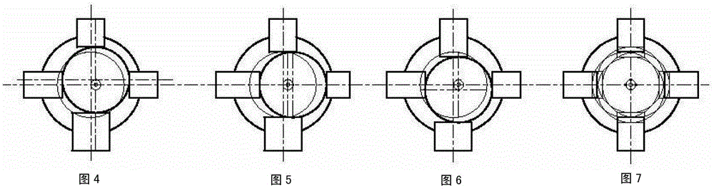
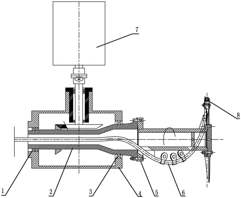
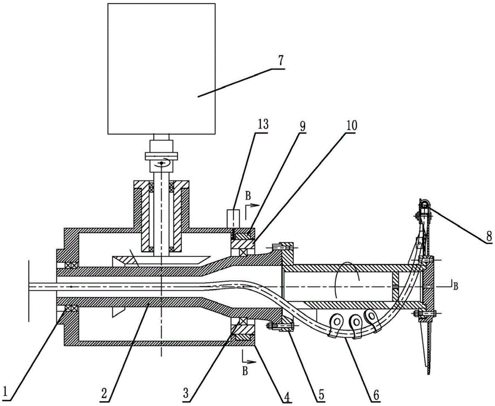
[0041] The present invention provides a spinning machine, which includes a box and a spinning head. The spinning head includes a spindle, and the spindle is installed in a boring hole of the box through a main bearing. The spinning machine also includes : An elastic mounting member, which is arranged on the box body and carries the main bearing, and is used to enable the main bearing to drive the main shaft to move in a predetermined range in a predetermined direction in the boring hole.

[0042] Specifically, in the laying machine of the present invention, in order to reduce the huge load and vibration caused by the rigid connection between the main bearing of the laying machine and the box of the laying machine, an elastic mounting member is added ...


PUM


Abstract

The invention provides a wire discharging machine. The wire discharging machine comprises a box body and a wire discharging head, wherein the wire discharging head comprises a main shaft, and the main shaft is mounted in a bore hole of the box body through a main bearing. The wire discharging machine further comprises an elastic mounting member, wherein the elastic mounting member is arranged on the box body, supports the main bearing and is used for enabling the main bearing to drive the main shaft to achieve the movement of a predetermined range in the bore hole along a predetermined direction. The elastic mounting member can offset vibration generated during the operation of the main bearing; a load caused by the high-frequency vibration and shock of the main bearing is reduced, the service life of the main bearing and the service life of the wire discharging head are prolonged, the operating efficiency of the wire discharging head is increased, and the production and repair costs are reduced. According to the embodiments of the invention, a flexible support is increased by the main bearing, and the high-speed operation is more stable, so that the wire discharging speed of the wire discharging machine can be increased, and then, the yield of a high-speed wire production line is increased.

Description

Technical field [0001] The invention relates to a high-speed wire rod production line in the field of steel rolling, and a wire laying machine that makes high-speed linearly moving hot-rolled wire rods form ring coils. Background technique [0002] At present, the high-speed wire rod production line that produces hot-rolled wire rod with a diameter of 5-25mm is generally used. After the hot steel billet is rolled by multiple rolling mills, it is finally rolled into a wire rod with a diameter of 5-25mm. The high-speed running wire forms a loop coil for collection. The maximum speed of the wire can reach 90-120m / s, and the speed of the output shaft of the laying machine can reach 1800 rpm. [0003] Reference figure 1 As shown, in the prior art, the main shaft 2 of the laying machine is installed in the box 4 of the laying machine through the radial thrust bearing 1 and the main bearing 3, and the front end of the main shaft 2 is connected with the spinning disk 5. The spinning tube...

Claims


Application Information

Patent Timeline
Patent Type & Authority Patents(China)
IPC IPC(8): B21H1/06
Inventor 刘炜陈南宁姚双吉
Owner BEIJING JINGCHENG RUIXINCHANGCAI ENG TECH
Why Eureka
Try Eureka