


Quick Research
Generate reliable direction feasibility study reports for your R&D in just a few steps.

Technical Q&A
Discover and master advanced knowledge NOW. Basics, ideas, possibilities, all at once.

Find Solutions
As an expert in R&D theories, this can generate solutions to your technical problems instantly.

Evaluate Feasibility
Analyze your overall solution with one click, know your potential R&D risks in advance.

Monitor Landscape
Get weekly tech updates, stay abreast of the latest tech innovations and key insights.
Exhaust pipe bending method
An exhaust pipe, straight pipe technology, applied in the field of pipe bending devices, can solve the problems of metal fatigue, corrosion, environmental pollution, etc., and achieve the effect of prolonging the service life, ensuring stable movement, and ensuring force balance
- Summary
- Abstract
- Description
- Claims
- Application Information
AI Technical Summary
Problems solved by technology
Method used
Image

Examples
Embodiment 1
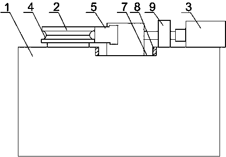
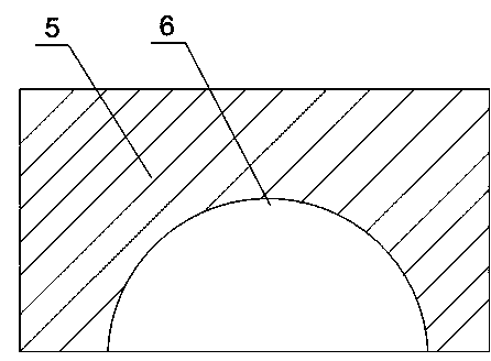
[0024] Such as Figure 1 to Figure 4 As shown, a method for bending an exhaust pipe of the present invention, the straight pipe piece 17 of the exhaust pipe is placed on the annular groove on the column 2, the hydraulic cylinder 3 is started, and the output end of the hydraulic cylinder 3 pushes the stopper 5 to slide The groove 7 moves toward the column 2. When the stopper 5 contacts the column 2 and clamps the straight pipe 17, the two walls of the semicircular groove 6 and the roller 10 on the bottom of the groove contact the straight pipe 17, and the hydraulic cylinder 3 continues to slide. Move in the groove 7, with the arc top of the side of the annular groove facing the stopper 5 as the support point, the two ends of the semicircular groove 6 respectively apply a force to the straight pipe piece 17, so that the straight pipe piece 17 begins to bend and deform, and the annular groove Cooperate with the semicircular groove 6, so that the straight pipe 17 gradually deforms...
Embodiment 2
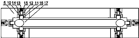
[0026] Such as figure 1 and image 3As shown, the present embodiment is based on Embodiment 1, and the damping structure includes a roller 10 support and a support cylinder 11, the support cylinder 11 is fixed in the semicircular groove 6, and the roller 10 is arranged on the roller 10 support through the rotating shaft 16. The bottom of the roller 10 bracket is provided with a support rod 13, the support rod 13 is installed in the support tube 11, the support rod 13 is provided with a limit block 14, and a torsion spring is installed between the limit block 14 and the bottom of the support tube 11 15. When the straight pipe piece 17 of the exhaust pipe is in contact with the two ends of the semicircular groove 6, under the propulsion of the hydraulic cylinder 3, the groove wall of the semicircular groove 6 and the roller 10 on the bottom of the groove begin to apply pressure to the straight pipe piece 17, and at the same time After the deformation of the pipe fitting 17, a ...
Embodiment 3
[0028] Such as image 3 As shown, in this embodiment, on the basis of Embodiment 1, the angle formed by the inner walls of the two ends of the semicircular groove 6 and the axis line of the roller 10 on the bottom of the groove is 60°. The distribution of the three rollers 10 on the semicircular groove 6 directly affects the stress of the straight pipe 17 of the exhaust pipe. The angle formed by the axis lines between the rollers 10 is 60°, so that the straight pipe 17 is placed in the semicircular groove 6. There are three evenly distributed stress points inside, and when the stopper 5 is pushed forward, the force balance of the straight pipe piece 17 is ensured, and indentation on the straight pipe piece 17 is avoided.
PUM
 Abstract
Description
Claims
Application Information
 - R&D Engineer
- R&D Manager
- IP Professional
- Industry Leading Data Capabilities
- Powerful AI technology
- Patent DNA Extraction
Browse by: Latest US Patents, China's latest patents, Technical Efficacy Thesaurus, Application Domain, Technology Topic, Popular Technical Reports.
© 2024 PatSnap. All rights reserved.Legal|Privacy policy|Modern Slavery Act Transparency Statement|Sitemap|About US| Contact US: help@patsnap.com