
Excitation circuit of electromagnetic flowmeter and electromagnetic flowmeter

An electromagnetic flowmeter and excitation circuit technology, applied in the direction of measuring flow/mass flow, liquid/fluid solid measurement, measuring devices, etc., can solve the problems of large flow value error, difficult electromotive force stable sampling, etc., to achieve rapid rise, Exciting current proceeds quickly and avoids damage

Active Publication Date: 2016-11-09
YAMATAKE HONEYWELL CO LTD
View PDF8 Cites 0 Cited by
  • Summary
  • Abstract
  • Description
  • Claims
  • Application Information

AI Technical Summary

Problems solved by technology

Therefore, it is difficult to stably sample the electromotive force, and as a result, the error of the flow rate value becomes large

Method used


Image

  • Excitation circuit of electromagnetic flowmeter and electromagnetic flowmeter
  • Excitation circuit of electromagnetic flowmeter and electromagnetic flowmeter
  • Excitation circuit of electromagnetic flowmeter and electromagnetic flowmeter

Examples


Embodiment Construction

[0054] Next, embodiments of the present invention will be described with reference to the drawings.

[0055] [First Embodiment]

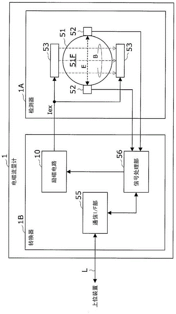
[0056] First, refer to figure 1 The electromagnetic flowmeter according to the first embodiment of the present invention will be described.

[0057] Such as figure 1 As shown, the electromagnetic flowmeter 1 is composed of a detector 1A and a switch 1B.

[0058] In the detector 1A, a measuring tube 51 , an electrode 52 , and an excitation coil 53 are provided as main components.

[0059] The measuring tube 51 is made of a cylindrical body of non-magnetic metal such as stainless steel as a whole, and forms a flow path 51F in which a fluid to be measured flows.

[0060] The exciting coil 53 is constituted by a pair of coils arranged opposite to the outside of the measuring tube 51, and has a function of making the magnetic field B perpendicular to the flow direction of the fluid flowing in the flow path 51F according to the exciting current Iex ...


PUM


Abstract

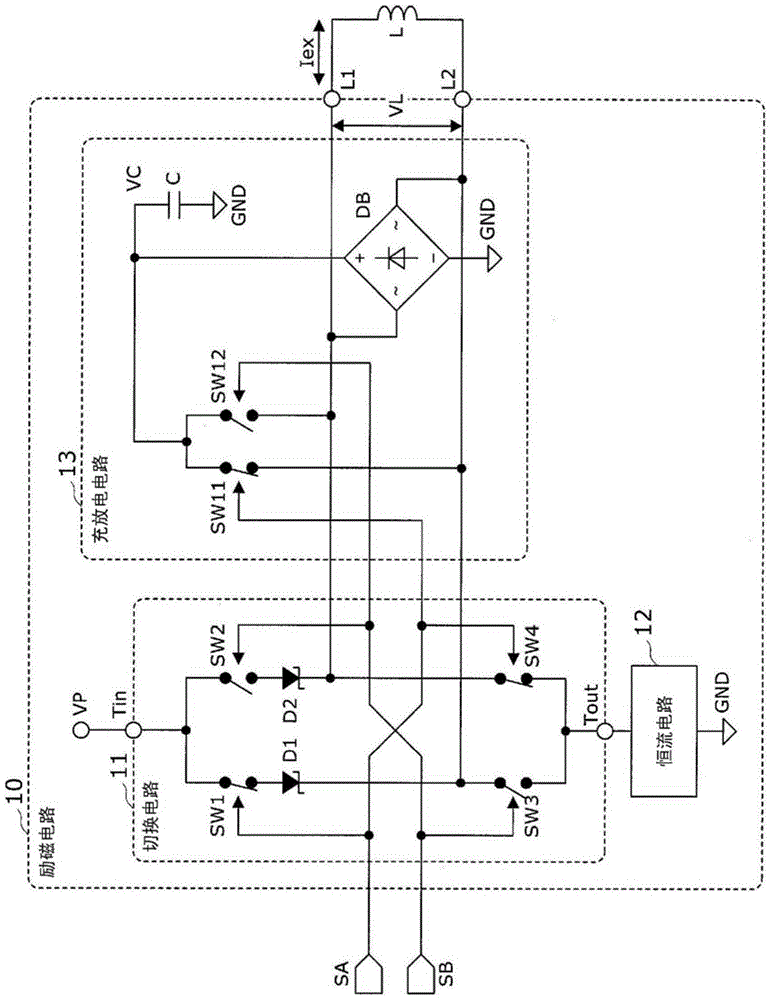
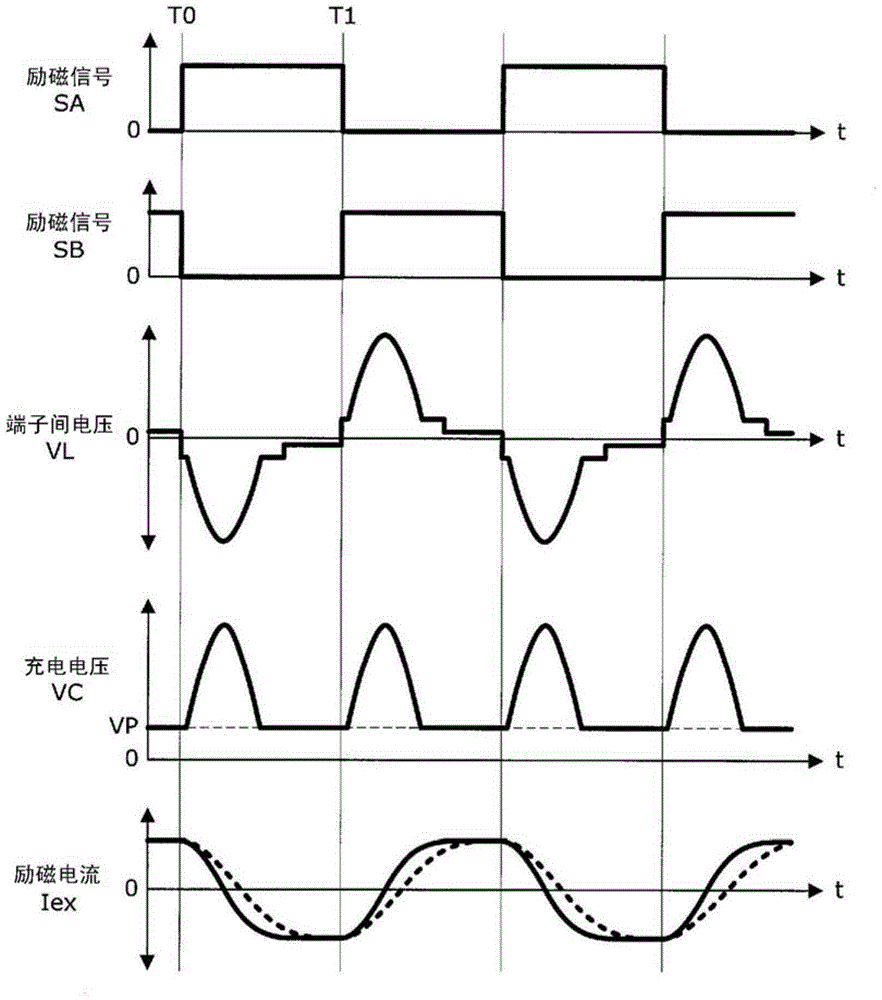
The present invention relates to an excitation circuit and an electromagnetic flowmeter for measuring the flow rate of a fluid having conductivity in various process systems. In this exciting circuit, the switching circuit (11) uses the driving current flowing from the current input terminal (Tin) to the current output terminal (Tout) through the diodes (D1, D2) as the exciting current ( Iex) is switched to the exciting coil (L), and the charging and discharging circuit (13) charges the counter electromotive force from the exciting coil (L) to the capacitive element (C) through the diode bridge (DB), and passes through the high withstand voltage state (SW1 , SW2), the discharge current from the capacitive element (C) is supplied to the exciting coil (L) in accordance with the polarity of the exciting current (Iex). Accordingly, while avoiding damage to the switching circuit due to high voltage, the counter electromotive force of the exciting coil can be effectively used to rapidly increase the exciting current.

Description

technical field [0001] The present invention relates to an excitation circuit of an electromagnetic flowmeter for measuring the flow rate of a conductive fluid in various process systems, and an electromagnetic flowmeter including the excitation circuit. Background technique [0002] In general, in an electromagnetic flowmeter that measures the flow rate of a conductive fluid, an excitation current whose polarity is alternately switched is supplied to an excitation coil, and a pair of magnets arranged in a measuring tube perpendicular to the magnetic field generated from the excitation coil are detected. The electromotive force generated between the electrodes is amplified, and the flow rate of the fluid flowing through the measuring tube is measured through sampling signal processing. The excitation coil is configured so that the direction of the magnetic field is perpendicular to the The flow direction of the flowing fluid. [0003] Such as Figure 5 As shown, the electro...

Claims


Application Information

Patent Timeline
Patent Type & Authority Patents(China)
IPC IPC(8): G01F1/60
CPCG01F1/60G01F1/588
Inventor 百濑修泽田秀雄光武一郎山崎吉夫
Owner YAMATAKE HONEYWELL CO LTD
Learn More