
Patsnap Eureka
For R&D, Patsnap Eureka makes reading and utilizing patents & technical documents easy.
Patsnap Eureka AIR
Designed for self-driven R&D workflows. Generate viable solutions, solve complex R&D challenges, empower your innovation with AI.

Patsnap Eureka Materials
Designed for material experts only. Revolutionize your material R&D, from search, analyze, to developing new materials.

TechResearch
Generate reliable direction feasibility study reports for your R&D in just a few steps.

TechSeek
Discover and master advanced knowledge NOW. Basics, ideas, possibilities, all at once.

TechMind
As an expert in R&D Theories, TechMind can generates customized viable solutions instantly.

TechRisk
Analyze your overall solution with one click, know your potential R&D risks in advance.

TechMonitor
Get weekly tech updates, stay abreast of the latest tech innovations and key insights.
An automatic decoupling sling
A technology of automatic decoupling and lifting gear, applied in the direction of load hanging components, transportation and packaging, etc., can solve problems such as difficulty in backfilling earthwork, large mechanical equipment, and inability to meet construction needs, etc., and achieve the effect of simple structure
- Summary
- Abstract
- Description
- Claims
- Application Information
AI Technical Summary
Problems solved by technology
Method used
Image

Examples
Embodiment Construction
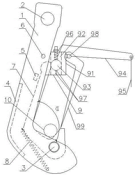
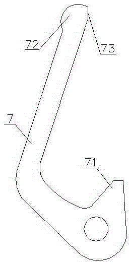
[0019] like figure 1 , figure 2 The shown automatic unhooking hanger includes two main hooks 1 whose lower parts are connected symmetrically by the auxiliary hook shaft 3, and a lifting hole 2 is provided on the upper end of the main hook 1, and the inner edge angle α of the main hook 1>90° , to meet the critical angle at which the weight is automatically slid. Hinged on the auxiliary hook shaft 3 is an auxiliary hook 7 positioned between the two main hooks 1, the upper end of the auxiliary hook 7 is provided with a contact 72, and the lower end is provided with a hook tip 71 protruding upwards from the inner edge of the main hook 1. One side of the head 72 is provided with a sliding section 73 tangent to the sliding part of the sliding pin 93 , and the sliding section 73 is located in the vertical plane. The outer edge of the auxiliary hook 7 is provided with a return extension spring 8, and the other end of the return extension spring 8 is fixed on the inner wall of the m...
PUM
 Abstract
Description
Claims
Application Information
 - R&D Engineer
- R&D Manager
- IP Professional
- Industry Leading Data Capabilities
- Powerful AI technology
- Patent DNA Extraction
Browse by: Latest US Patents, China's latest patents, Technical Efficacy Thesaurus, Application Domain, Technology Topic, Popular Technical Reports.
© 2024 PatSnap. All rights reserved.Legal|Privacy policy|Modern Slavery Act Transparency Statement|Sitemap|About US| Contact US: help@patsnap.com