
Clock synchronizing method for wireless sensing network

A technology of wireless sensor network and clock synchronization, which is applied in the direction of synchronization device, synchronization device, wireless communication, etc., and can solve problems such as the influence of measurement accuracy

Inactive Publication Date: 2014-11-19
TAIYUAN UNIV OF TECH
View PDF1 Cites 23 Cited by
  • Summary
  • Abstract
  • Description
  • Claims
  • Application Information

AI Technical Summary

Problems solved by technology

However, the drift rate caused by clock aging is still an unavoidable problem, and the clock drift compensation algorithm is essential
The clock of most microcontrollers is driven by a crystal oscillator. For a commercial crystal oscillator, its frequency usually varies within 10-100ppm of its nominal value, so the relative clock drift between nodes may reach 200ppm. When measuring a long time interval, the relative clock drift will have a more obvious impact on the measurement accuracy

Method used


Image

  • Clock synchronizing method for wireless sensing network
  • Clock synchronizing method for wireless sensing network
  • Clock synchronizing method for wireless sensing network

Examples


Embodiment Construction

[0049] The invention solves the problem of clock deviation in a synchronous period caused by the jitter of a crystal oscillator in a wireless sensor network. The present invention is realized by adopting the following technical solutions:

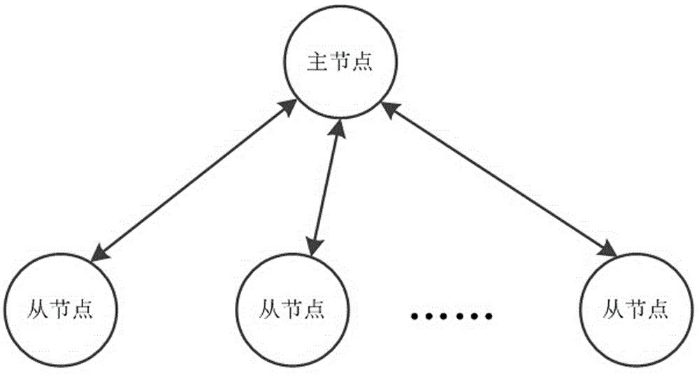
[0050] as attached figure 1 As shown, the wireless sensor network includes a master node and n slave nodes, and the method includes the following steps:

[0051] Step 1: Clock drift rate ρ for slave node n n To model:

[0052] ρ n (k) = ρ n (k-1)+v(k);

[0053] ρ n * (k) = ρ n (k)+w(k);

[0054] Among them, ρ n ρ n * (k) is the clock drift rate of node n measured during the kth synchronization relative to the master node; w(k) is a normal distribution random variable with zero mean value, representing measurement noise;

[0055] Step 2: Use the previous state of the model to predict the current state:

[0056] ρ ^ n ( k |...


PUM


Abstract

The invention discloses a time synchronizing method for a wireless sensor network, and belongs to the technical field of wireless sensor networks. According to the technical scheme of the invention, the network comprises a master node and n slave nodes, the slave nodes perform relative clock drift estimation, and master and slave node clock synchronization is performed between the master node and the slave nodes by exchanging synchronization messages in order to compensate for a clock deviation caused by a crystal oscillator, so that local clocks of the slave nodes are regulated to realize accurate synchronization of a main node clock. By adopting the time synchronizing method, time drift caused by the crystal oscillator can be suppressed effectively, and the clock synchronizing accuracy among network nodes is increased.

Description

technical field [0001] The invention belongs to the technical field of wireless sensor networks, in particular to a time synchronization method of wireless sensor networks. Background technique [0002] Wireless sensor networks (Wireless Sensor Networks, WSN) are composed of a large number of sensor nodes, usually deployed in unattended monitoring areas, obtain monitoring information in a self-organizing and collaborative manner, and send the processed information to end users, WSN It has been widely used in many fields such as military, industry, agriculture and medical treatment. [0003] In a wireless sensor network, different nodes have their own local time. Due to the deviation (frequency deviation) of the crystal oscillator frequency of different nodes, and with the change of temperature, voltage, air pressure, etc. and the aging of the oscillator, it will also Causes the natural frequency of the oscillator to drift (frequency drift). Therefore, the time synchronizat...

Claims


Application Information

Patent Timeline
Patent Type & Authority Applications(China)
IPC IPC(8): H04L7/00H04W56/00
Inventor 李艳萍郭丽芳陈相南任腾飞赵晓丽张博叶郝喜国
Owner TAIYUAN UNIV OF TECH
Learn More