
Swing rod mechanism of rocket launching platform and swing rod applied to mechanism

A technology for a rocket launch platform and a launch platform, which is applied in the field of equipment for rocket launch platforms, can solve the problems of manpower, material resources and time, main shaft stuck, weak carrying capacity, etc., to reduce the scale of the system, ensure mechanical strength, and facilitate swinging Effect

Inactive Publication Date: 2014-11-19
BEIJING INST OF SPACE LAUNCH TECH +1
View PDF3 Cites 15 Cited by
  • Summary
  • Abstract
  • Description
  • Claims
  • Application Information

AI Technical Summary

Problems solved by technology

[0006] The swing rod in the prior art is a complete truss, and the material of the swing rod in the prior art is made of special steel, which is relatively heavy, resulting in a weak bearing capacity, and the use of pipelines, connectors, and cables The amount is limited, and it is not conducive to the rapid swinging and braking of the pendulum. In addition, the pendulum in the prior art is integral, and its curvature cannot be adjusted. It cannot meet the rocket launch requirements of various shapes and specifications. When the rocket body is of different specifications, it is necessary to design swing rods of different structures and to replace the swing rods. This design or replacement work will consume a lot of manpower, material resources and time to a certain extent, which will affect the launch progress of the rocket.
[0007] In addition, in the prior art, the umbilical tower is installed on the movable launch platform. The umbilical tower is a slender and towering tower structure with poor rigidity and is easily deformed after being loaded, causing the support on the main shaft to move, which may cause the main shaft to get stuck, causing Movement faults, light ones will cause damage to related parts, and severe ones may even make the pendulum bar unable to complete the swing motion. Therefore, the pendulum bar mechanism in the prior art is in urgent need of modification to ensure the smooth and safe operation of the mechanism

Method used


Image

  • Swing rod mechanism of rocket launching platform and swing rod applied to mechanism
  • Swing rod mechanism of rocket launching platform and swing rod applied to mechanism
  • Swing rod mechanism of rocket launching platform and swing rod applied to mechanism

Examples


Embodiment Construction

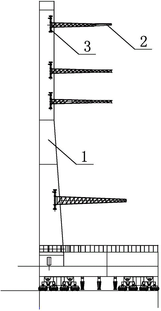
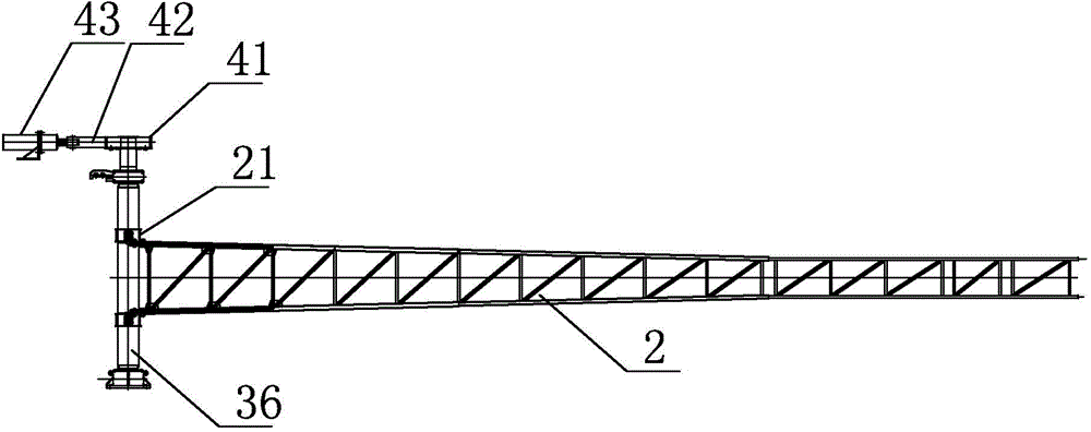
[0025] Such as Figure 1-2 As shown, the swing rod mechanism of the rocket launch platform of the present invention is installed on the umbilical cord tower 1 of the launch platform, and is located on both sides of the umbilical cord tower 1, and is used to carry and release gas supply pipelines and satellite cables, including the swing rod 2, the swing rod 2 The connecting device 3 connected to the umbilical tower 1 and the driving device 4 that drives the swing rod 2 to rotate. The swing rod 2 is an arc-shaped swing rod 2 hinged by multi-section trusses. The end of the swing rod 2 close to the umbilical tower 1 is hinged. The end is connected with the connection device 3. Preferably, the swing rod 2 is hinged by three sections of trusses. The truss section at the hinged end of the swing rod 2 is made of Q345 steel, and the rest of the truss sections are made of 2A14 aluminum alloy.

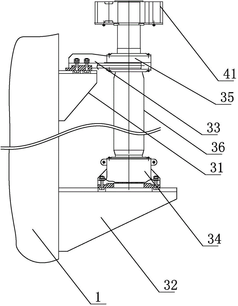
[0026] Such as image 3 As shown, the connecting device 3 includes an upper mounting base 3...


PUM


Abstract

The invention discloses a swing rod mechanism of a rocket launching platform and a swing rod applied to the mechanism and relates to equipment for the rocket launching platform. The swing rod mechanism is mounted on the umbilical tower of the launching platform and used for bearing a feed-discharge gas supply pipeline and a satellite cable. The swing rod mechanism comprises the swing rod, a connecting device for connecting the swing rod to the umbilical tower and a drive device for driving the swing rod to rotate. The drive device comprises a rack for driving a driven gear, a hydraulic oil cylinder connected with the rack and a hydraulic control system for controlling the hydraulic oil cylinder. The hydraulic oil cylinder drives the swing rod to rotate sequentially through the rack, the driven gear and a rotary shaft.

Description

technical field [0001] The invention relates to a device for a rocket launching platform, in particular to a swing rod mechanism for carrying and swinging a gas supply pipeline for adding and releasing gas and satellite cables. Background technique [0002] The effect of the pendulum mechanism in the prior art mainly includes: [0003] 1) Lay various filling, exhaust, cable and other pipelines on the pendulum of the technical workshop to connect various connectors with the rocket body; [0004] 2) During the transportation process, the pendulum keeps the connection state of various pipelines, connectors and cables used to connect the rocket body and the launch platform unchanged; [0005] 3) Two minutes before the launch of the rocket, the pendulum quickly swings the various pipelines and connectors that have fallen off the rocket body to a safe area, providing a safe take-off channel for the rocket. [0006] The swing rod in the prior art is a complete truss, and the mate...

Claims


Application Information

Patent Timeline
IPC IPC(8): F41F3/04
Inventor 潘玉竹贾永涛冯超吴梦强任晓伟黎定仕高亚东丁保民刘学慧徐铮刘丽媛林辉崔浏吴新跃
Owner BEIJING INST OF SPACE LAUNCH TECH
Learn More