
Gas Turbine Dual Fuel Nozzle Structure

A gas turbine and dual-fuel technology, applied in combustion chambers, combustion methods, combustion equipment, etc., can solve the problems of not being easy to burn and the difficulty of mixing fuel gas and air, and achieve good work and improve mixing efficiency

Active Publication Date: 2018-03-23
CHINA UNITED GAS TURBINE TECH CO LTD
View PDF8 Cites 0 Cited by
  • Summary
  • Abstract
  • Description
  • Claims
  • Application Information

AI Technical Summary

Problems solved by technology

For natural gas combustors, the volume flow rate of fuel gas accounts for 2-3% of the air flow rate in the combustor; while for the combustors with medium and low calorific value fuel gas, the volume flow rate of fuel gas accounts for 10%-20% of the air flow rate in the combustor. Therefore, by When the combustor transformed from natural gas combustor burns syngas, there will be problems such as difficulty in mixing fuel gas and air in the combustion area, and CO in low-to-medium calorific value fuel gas is not easy to burn completely.

Method used


Image

  • Gas Turbine Dual Fuel Nozzle Structure
  • Gas Turbine Dual Fuel Nozzle Structure
  • Gas Turbine Dual Fuel Nozzle Structure

Examples


Embodiment Construction

[0025] The specific implementation manners of the present invention will be further described in detail below in conjunction with the accompanying drawings and embodiments. The following examples are used to illustrate the present invention, but are not intended to limit the scope of the present invention.

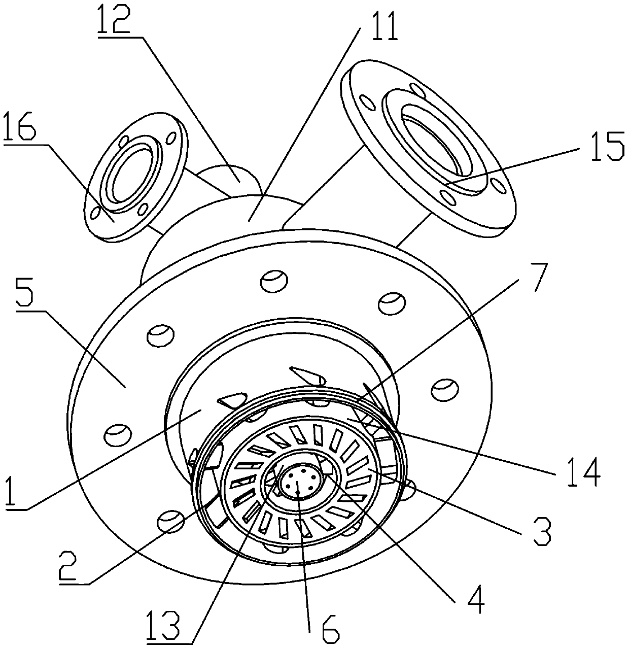
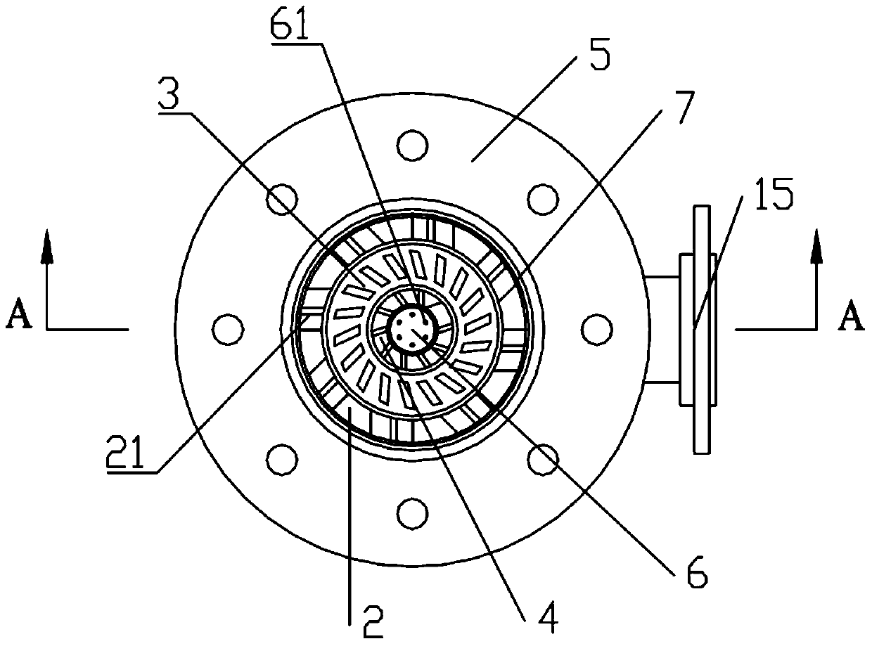
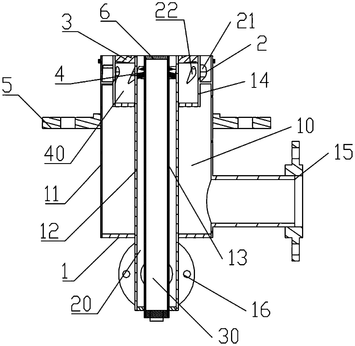
[0026] like Figures 1 to 3 As shown, the gas turbine dual-fuel nozzle structure of the present invention includes: a nozzle body 1, a low-medium calorific value fuel gas swirler 2, a natural gas swirler 4, and an end face swirler 3. The nozzle body 1 includes inner diameters that increase in sequence, and mutually Isolated light blowing air cylinder 13, natural gas cylinder 12, nozzle air cylinder 14 and medium and low calorific value fuel gas cylinder 11, the upper parts of light blowing air cylinder 13, natural gas cylinder 12, nozzle air cylinder 14 and medium and low calorific value fuel gas cylinder 11 are all openings , as the gas outlet, the bottom is sealed, and ...


PUM


Abstract

The invention relates to the technical field of gas turbines, and discloses a dual-fuel nozzle structure of a gas turbine. The dual-fuel nozzle structure of the gas turbine comprises a nozzle body, a medium-low heat value fuel gas whirlcone, a natural gas whirlcone and an end face whirlcone. The nozzle body comprises a slightly-blowing air barrel, a natural gas barrel, a nozzle air barrel and a medium-low heat value fuel gas barrel with the inner diameters being sequentially increased, and the barrels are isolated from one another. The end face whirlcone is arranged on the outlet end face of the nozzle air barrel. The natural gas whirlcone is arranged on the inner side wall of the natural gas barrel. The medium-low heat value fuel gas whirlcone is arranged on the inner side wall of the outlet end of the medium-low heat value fuel gas barrel, the medium-low heat value fuel gas whirlcone comprises a plurality of blades, and the blades are connected with the inner side wall of the medium-low heat value fuel gas barrel and the outer side wall of the nozzle air barrel. Each blade is provided with an air channel, and the air channels are communicated with the nozzle air barrel and an outside air flow channel of the medium-low heat value fuel gas barrel. An end face cover plate is arranged on the outlet end face of the slightly-blowing air barrel, and the end face cover plate is provided with a plurality of slightly-blowing air holes.

Description

technical field [0001] The invention relates to the technical field of gas turbines, in particular to a dual-fuel nozzle structure of a gas turbine. Background technique [0002] Heavy-duty industrial gas turbines for power generation have the characteristics of high efficiency and low pollution. The basic principle is to mix compressed air and fuel, and generate high-temperature and high-pressure gas through combustion to drive the turbine to do work. Part of the work is used to drive the compressor, and the other part is used as power output to drive the generator. . [0003] The combustor is one of the core components of the gas turbine. In the combustor, the gas compressed by the compressor is mixed with the fuel, and burns in it at approximately isobaric pressure. The chemical energy contained in the fuel is converted into heat energy in the gas. The outlet temperature of the combustor is divided One of the most important signs of gas turbine rating. [0004] Under th...

Claims


Application Information

Patent Timeline
Patent Type & Authority Patents(China)
IPC IPC(8): F23R3/38
Inventor 吕煊张珊珊李珊珊方子文
Owner CHINA UNITED GAS TURBINE TECH CO LTD
Learn More