Fan system

A fan system and sensing unit technology, applied in cooling/ventilation/heating transformation, pump control, non-variable pumps, etc., can solve the problem of communication chassis and servo cabinets unable to dissipate heat, uneven temperature, and excessive cavity weight And other issues

Active Publication Date: 2014-11-19
ASIA VITAL COMPONENTS SHENZHEN CO LTD
View PDF7 Cites 4 Cited by
  • Summary
  • Abstract
  • Description
  • Claims
  • Application Information

AI Technical Summary

Problems solved by technology

Therefore, it is easy to cause the heat emitted by the electronic equipment to accumulate and gather in the local area of ​​the chassis (cabinet), resulting in high temperature in the local area and difficult heat dissipation, which makes the temperature that the electronic device can tolerate beyond the limit range, which will seriously affect the The reliability and service life of some electronic equipment, however, in other large areas where the chassis (cabinet) cavity is far away from heat-generating electronic devices, the temperature is indeed much lower than that of the local area in contact with the electronic equipment.
Therefore, it is known from the above that the temperature of the chassis (cabinet) cavity is extremely uneven, which directly and seriously affects the overall heat dissipation performance of the chassis.
In view of the above problems, the existing solutions are generally to increase the size of the cavity or improve the material of the cavity, but at the same time it will bring technical problems such as excessive weight of the cavity, so how to maintain the size and weight of the chassis cavity without changing It is an important topic at present to improve its heat dissipation performance under the premise of the premise, so usually the main heat dissipation technical means of the communication chassis and the servo cabinet will use the cooling fan
[0003] In addition, there are a large number of communication boxes and servo cabinets in general, and the distribution of locations is extremely wide. When the cooling fans in each communication box and servo cabinet are damaged, it is difficult for maintenance personnel to come to the scene to replace them immediately, or their communication boxes and servo cabinets When a warning or an abnormality occurs due to the inability to dissipate heat, it means that the electronic equipment in the communication chassis and servo cabinet has no cooling fan for cooling, and the electronic equipment is not enough to use, which will cause the communication chassis and servo The cabinet is damaged and the maintenance cost is relatively increased

Method used


Image

  • Fan system
  • Fan system
  • Fan system

Examples


Embodiment Construction

[0045] The above-mentioned purpose of the present invention and its structural and functional characteristics will be described according to the preferred embodiments of the accompanying drawings.

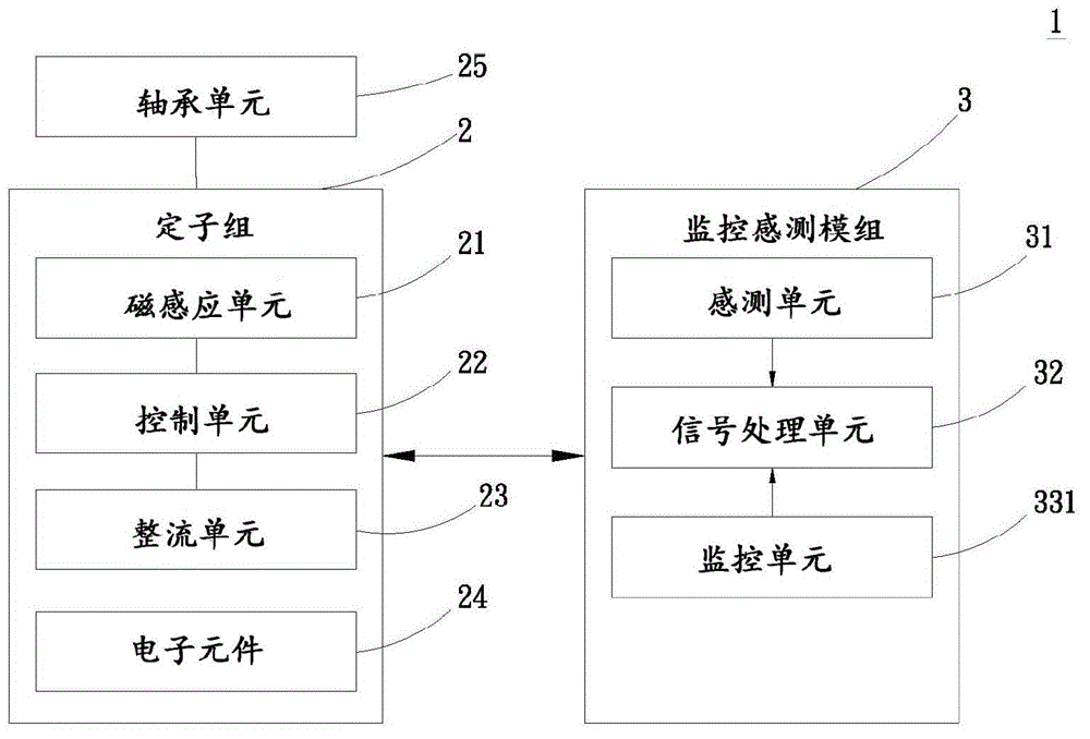
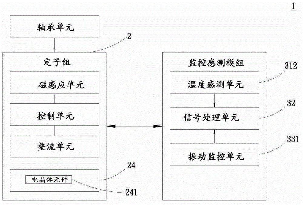
[0046] The present invention provides a fan system, please refer to figure 1 Shown is a schematic block diagram showing the first preferred embodiment of the present invention Figure 1 , wherein the fan system 1 includes a stator group 2 and a monitoring and sensing module 3 .

[0047] Wherein the stator group 2 includes a magnetic induction unit 21, a control unit 22, a rectification unit 23 and a plurality of electronic components 24 and is provided with a bearing unit 25. In this embodiment, its magnetic induction unit 21 is a Hall element, and the magnetic induction The unit 21 is electrically connected to the control unit 22, the control unit 22 is a microcontroller, and the control unit 22 is electrically connected to the rectification unit 23, and the rectification unit 23...


PUM


Abstract

The invention provides a fan system which comprises a stator set and a monitoring and sensing module. The stator set is electrically connected with the monitoring and sensing module. The monitoring and sensing module is provided with at least one sensing unit, at least one monitoring unit and a control unit. The sensing unit of the monitoring and sensing module senses the fan system, and a signal processing unit actively notifies and warns the service condition of a fan, so that the abnormal condition is avoided; moreover, the maintenance cost can be reduced.

Description

technical field [0001] The present invention relates to a fan, especially a fan system that can proactively inform and warn the usage status of the fan to avoid abnormal occurrence and reduce maintenance cost. Background technique [0002] According to the current electronic communication or server equipment, the known technology is arranged in a communication case and / or servo cabinet to run, and these devices will generate a heat source during operation, because the communication case and the servo cabinet are a closed body. Therefore, it is easy to cause the heat emitted by the electronic equipment to accumulate and gather in the local area of ​​the chassis (cabinet), resulting in high temperature in the local area and difficult heat dissipation, which makes the temperature that the electronic device can tolerate beyond the limit range, which will seriously affect the The reliability and service life of some electronic equipment, however, in other large areas where the ch...

Claims


Application Information

Patent Timeline
Patent Type & Authority Applications(China)
IPC IPC(8): F04D27/00H05K7/20
Inventor 廖翊宏臧崧翔林昱安
Owner ASIA VITAL COMPONENTS SHENZHEN CO LTD
Why Eureka
Try Eureka