Ring gear high frequency quenching process

A high-frequency quenching and ring gear technology, applied in the field of heat treatment, can solve problems such as the inability to realize the yin and yang face of the ring gear

Active Publication Date: 2016-07-06
山东盛祥智能制造有限公司
View PDF4 Cites 0 Cited by
  • Summary
  • Abstract
  • Description
  • Claims
  • Application Information

AI Technical Summary

Problems solved by technology

[0004] The technical problem to be solved by the present invention is to provide a ring gear high-frequency quenching process to solve the technical problem that the traditional high-frequency quenching process cannot realize the "yin and yang face" of the ring gear

Method used


Image

  • Ring gear high frequency quenching process
  • Ring gear high frequency quenching process
  • Ring gear high frequency quenching process

Examples


Embodiment Construction

[0019] The present invention will be further described below in conjunction with the accompanying drawings and embodiments.

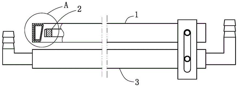
[0020] like figure 1 and Figure 4 Commonly shown, a ring gear high-frequency quenching process includes the following steps:

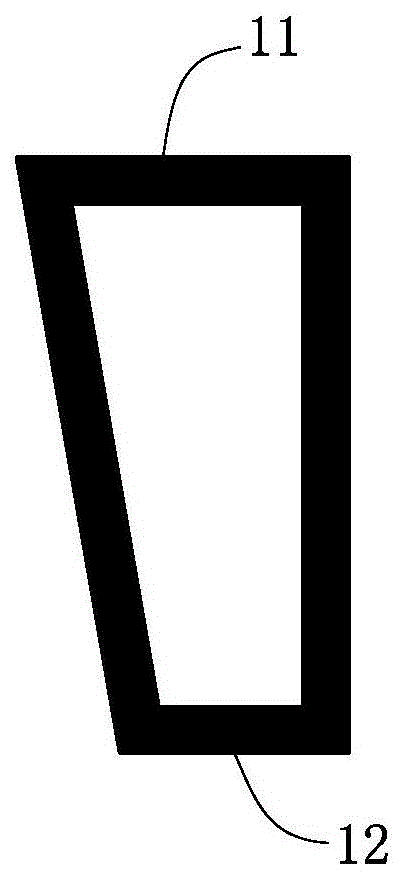
[0021] a, adjust the cross-sectional shape of the quenching induction coil 1, so that the cross-sectional shape of the quenching induction coil 1 is a right-angled trapezoid (such as image 3 As shown), the outer peripheries of the three right-angled sides of the quenching induction coil 1 are covered with magnetizers 13, and the magnetizers 13 shield the magnetic field to reduce energy loss and play an energy-saving role. The quenching induction coil 1 is placed horizontally and the quenching induction coil 1 The long right-angled side 11 of the ring gear 2 faces upward, and the ring gear 2 is placed in the quenching induction coil 1 with the chamfered end face 21 of the ring gear 2 facing upward;

[0022] b. For the first...


PUM

PropertyMeasurementUnit
thicknessaaaaaaaaaa

Abstract

The invention discloses a gear ring high frequency quenching process and belongs to the technical field of thermal treatment. The gear ring high frequency quenching process comprises the following steps: a, adjusting the cross section shape of a quenching induction coil to be a right trapezoid, placing the quenching induction coil horizontally with the long right angle side of the quenching induction coil facing upwards, and putting a gear ring within the quenching induction coil with the chamfered end face of the gear ring facing upwards; b, carrying out first quenching, considering the drop height of the long right angle side of the quenching induction coil to the chamfered end face of the gear ring as a first setting distance, setting the heating time as a first setting time, and setting the cooling time as a second setting time; c, carrying out second quenching, considering the drop height of the short right angle side of the quenching induction coil to the non-chamfered end face of the gear ring as a second setting distance, setting the heating time as a third setting time, and setting the cooling time as a fourth setting time. The gear ring high frequency quenching process solves the technical problem that the traditional high frequency quenching process cannot realize "different faces" of the gear ring and is widely used in thermal treatment.

Description

technical field [0001] The invention relates to the technical field of heat treatment, in particular to a ring gear high-frequency quenching process. Background technique [0002] The ring gear must be heat-treated after machining to improve its surface hardness and wear resistance. At present, the commonly used heat treatment process is high-frequency quenching. High-frequency quenching is mostly used for surface quenching of industrial metal parts. A metal heat treatment method that induces current, rapidly heats the surface of the part, and then rapidly quenches it. The equipment used is a high-frequency quenching inductor. The principle of induction heating: the workpiece is placed in the inductor, and the inductor is generally a hollow copper tube that inputs intermediate frequency or high frequency alternating current (1000-300000Hz or higher), such as figure 2 As shown, the copper tube is made into a square tube shape, and the shaped mold is quickly completed under t...

Claims


Application Information

Patent Timeline
Patent Type & Authority Patents(China)
IPC IPC(8): C21D9/40C21D9/32C21D1/10
CPCY02P10/25
Inventor 李金年杨明军李同明
Owner 山东盛祥智能制造有限公司
Why Eureka
Try Eureka