Gas separation unit

A technology of gas separation and gas inlet, applied in the direction of fractionation, can solve the problems of poor gas separation effect and insufficient gas-liquid contact, etc., and achieve the effect of reducing insufficient gas-liquid contact

Inactive Publication Date: 2014-11-19
SUZHOU XINGLU AIR SEPARATION PLANT SCI & TECH DEV CO LTD
View PDF6 Cites 0 Cited by
  • Summary
  • Abstract
  • Description
  • Claims
  • Application Information

AI Technical Summary

Problems solved by technology

[0003] The purpose of the invention is to solve the technical problem that the gas-liquid cannot be fully contacted in the bumpy and shaking environment of the gas separation device, resulting in poor gas separation effect

Method used


Image

  • Gas separation unit
  • Gas separation unit

Examples


Embodiment Construction

[0011] Preferred embodiments of the gas separation device of the present invention will be described in detail below in conjunction with the accompanying drawings.

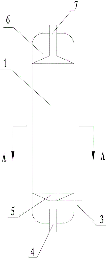
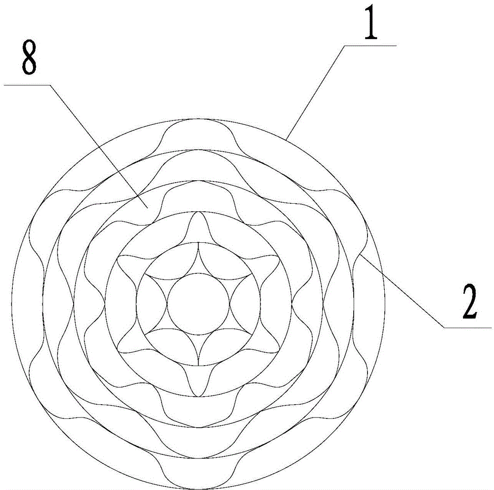
[0012] See attached Figure 1-2 , the gas separation device of the present invention comprises a rectification tower 1, a filler 2 filled in the rectification tower 1, a gas inlet 3 and a liquid outlet 4 are provided at the bottom of the rectification tower 1, and a gas inlet 3 and a liquid outlet 4 are arranged at the top of the rectification tower 1. Cold source 6, gas outlet 7. Among them, the filler 2 penetrates up and down, so that the gas and liquid can flow up and down along the penetration direction of the filler. The cross section of the filler 2 is composed of a plurality of interconnected filler lattices. As a preferred solution, the cross section of the filler 2 is a plurality of concentric Circle, between two adjacent concentric circles is divided into multiple disconnected packing grids through wavy...


PUM


Abstract

The invention discloses a gas separation unit. The gas separation unit comprises a rectifying tower. The interior of the rectifying tower is filled with a filling material which is through from top to bottom; the bottom of the rectifying tower is provided with a gas inlet and a liquid outlet; the top of the rectifying tower is provided with a cold source and a gas outlet; and the gas inlet, the liquid outlet and the gas outlet are all communicated with the interior of the rectifying tower. The gas separation unit is characterized in that the cross section of the filling material is divided into a plurality of mutually different filling material grids, and the bottom of the rectifying tower is further provided with a gas distributor which is used for uniformly distributing gas introduced from the gas inlet into the bottom end of the filling material. The gas separation unit can guarantee that the rectification effect of gas is not affected in a range of 7.5 DEG inclination from any direction, and the gas separation unit is applicable to specific bumpy working environments like a ship.

Description

technical field [0001] The invention relates to a gas separation device capable of tilting and swinging. Background technique [0002] General gas separation devices use the different boiling points of different gases to sequentially liquefy the different gas components in the gas to be separated through heat exchange, and pressurize them into tanks. Distillation towers are often used here. There is a filler that penetrates up and down inside. The upper end of the rectification tower is equipped with a cold source. The gas to be separated flows from the lower end of the rectification tower to the upper end. When it flows to the upper end, it meets the cold source. At this time, the gas with a higher boiling point will be liquefied. It then flows down the sidewall of the packing, where the liquid meets the upwardly flowing gas. If the rectification tower is tilted at this time, the liquid gas flowing from top to bottom will inevitably flow to one side, resulting in uneven di...

Claims


Application Information

Patent Timeline
Patent Type & Authority Applications(China)
IPC IPC(8): B01D3/14
Inventor 肖龙昆叶秋芳丁国元孙宁刘志洲贾盛兰
Owner SUZHOU XINGLU AIR SEPARATION PLANT SCI & TECH DEV CO LTD
Why Eureka
Try Eureka