
Gas mixer and gas mixing system

A gas mixer and gas technology, applied in the direction of gas and gas/steam mixing, fluid mixer, mixer, etc., can solve the problems of poor overall efficiency and other problems

Inactive Publication Date: 2014-11-12
ROLLS ROYCE SOLUTIONS GMBH
View PDF11 Cites 4 Cited by
  • Summary
  • Abstract
  • Description
  • Claims
  • Application Information

AI Technical Summary

Problems solved by technology

This total pressure loss must be eliminated periodically by the compressor of the exhaust gas turbocharger, which is usually arranged after the gas mixer; that is to say, the power produced by the compressor changes with the total pressure loss, which makes the configuration Deterioration of the overall efficiency of gas mixing systems of internal combustion engines with gas mixers, especially with gas engines, etc.

Method used


Image

  • Gas mixer and gas mixing system
  • Gas mixer and gas mixing system

Examples


Embodiment Construction

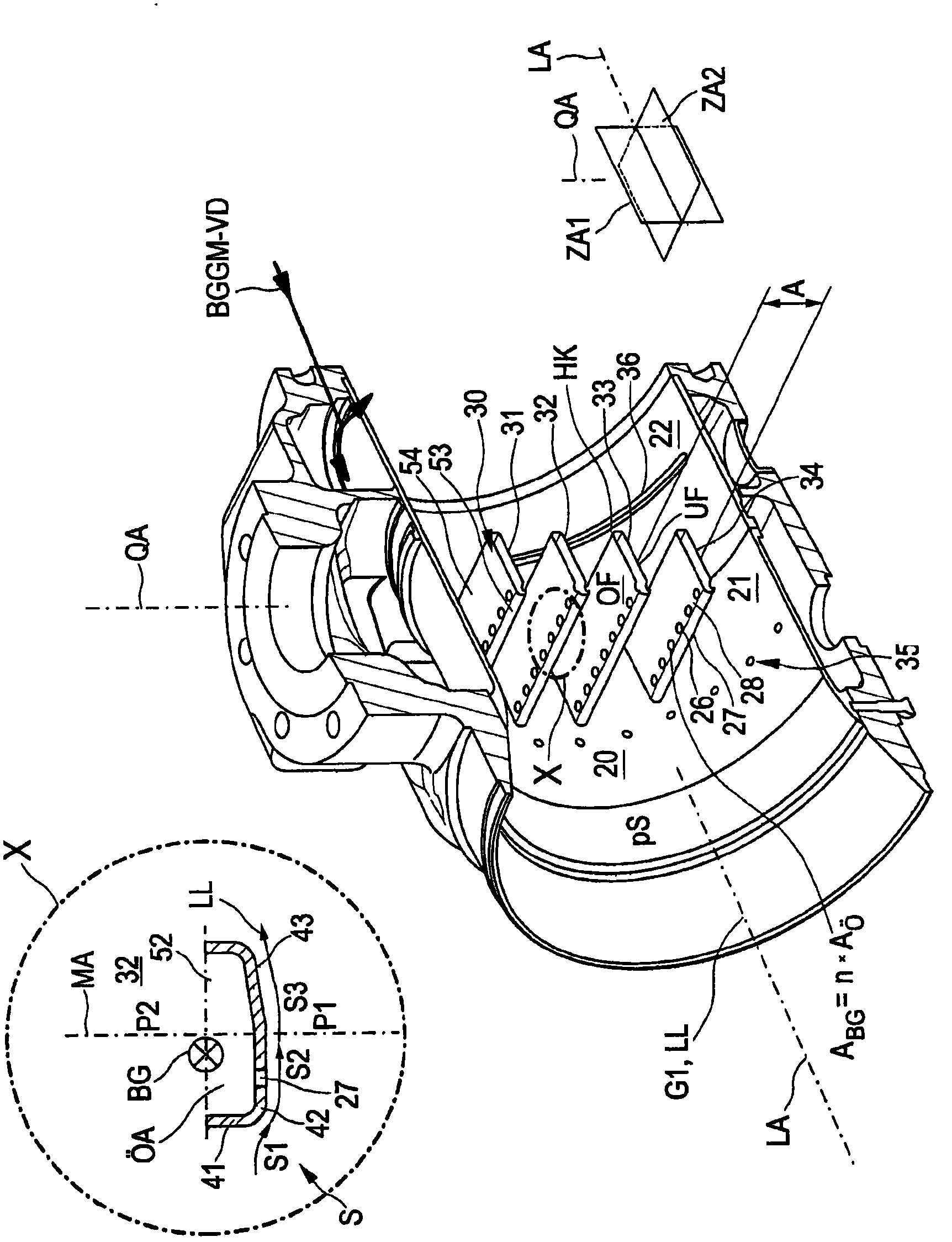
[0035] figure 1 Shown is a gas mixing system 1000 with a gas mixer 100 for mixing a first gas G1 - charge air LL in this embodiment and a second gas G2 - in this embodiment combustible gas LL, for a gas engine 400 Gas BG. The gas mixture G3 formed by the first gas G1 and the second gas G2 - in this embodiment a combustible gas mixture BGGM - is supplied to a compressor 300 and finally in compressed form to an internal combustion engine which in this embodiment A gas engine 400 with cylinders 1 , 2 , 3 , 4 is shown symbolically in FIG. Combustible gas mixture BGGM combusted for work in gas engine 400 is discharged as exhaust gas AG into an exhaust gas recirculation system and, if necessary, into the environment via an exhaust gas aftertreatment system, which will not be explained further. In this embodiment shown, the gas mixer 100 is incorporated into a high pressure recirculation system 310 . The pressure regulator 320 serves in this embodiment to power the gas engine 400 ...


PUM


Abstract

A gas mixer for mixing a first gas and a second gas, having a first, outer gas housing part, having an inlet for the first gas in a longitudinal axis and an inlet for the second gas in a transverse axis, a second, interior gas housing part set into the first gas housing part to form an annular space for a second gas, having a mixing space into which the first gas and the second gas are introduced for mixing. The first and second gas housing parts and the annular space are aligned along the longitudinal axis and the mixing space is aligned cylindrically along the longitudinal axis. A mixing device having a plurality of hollow rods is arranged in the mixing space. A hollow space of a hollow rod is in fluid communication on both sides with the annular space. The number of hollow rods extends transverse to the longitudinal axis and the transverse axis and at least one hollow rod has a plurality of openings for the second gas, so that the hollow space is in fluid communication with the cylindrical mixing space.

Description

technical field [0001] The invention relates to a gas mixer according to the preamble of claim 1 . The gas mixer has: a first outer gas housing part with an infeed for a first gas in the longitudinal axis and an infeed for a second gas in the transverse axis; In the case of an annular chamber for the second gas is encased in a second inner gas housing part within the first gas housing part, said second inner gas housing part comprising a mixing chamber in which the first gas and the second gas can be is introduced into the mixing chamber for mixing into a gas mixture, wherein the first gas housing part and the second gas housing part and the annular cavity are oriented along the longitudinal axis, and the mixing chamber is oriented cylindrically along the longitudinal axis, In this case, a mixing device having a plurality of hollow rods is arranged in the mixing chamber, wherein the cavities of the hollow rods are fluidically connected to the annular space on both sides. The...

Claims


Application Information

Patent Timeline
Patent Type & Authority Applications(China)
IPC IPC(8): B01F3/02B01F5/04F02M21/04B01F23/10
CPCB01F5/0428B01F3/026B01F5/0682B01F3/02F02M21/047B01F2005/0094B01F5/0421B01F5/0426Y02T10/32F02M21/042Y02T10/30B01F23/10B01F25/31232B01F25/31241B01F25/31242B01F23/19B01F25/45B01F2025/932
Inventor M·莱茵德尔
Owner ROLLS ROYCE SOLUTIONS GMBH
Learn More