
Electric connection method for motor stator and coil of motor stator

A motor stator and electrical connection technology, which is applied to electrical components, electromechanical devices, electrical components, etc., can solve the problems of increasing the manufacturing and use cost of positioning fixtures, not meeting economic benefits, and unable to cooperate with each other.

Inactive Publication Date: 2014-11-12
SUNON ELECTRONICS KUNSHAN
View PDF5 Cites 2 Cited by
  • Summary
  • Abstract
  • Description
  • Claims
  • Application Information

AI Technical Summary

Problems solved by technology

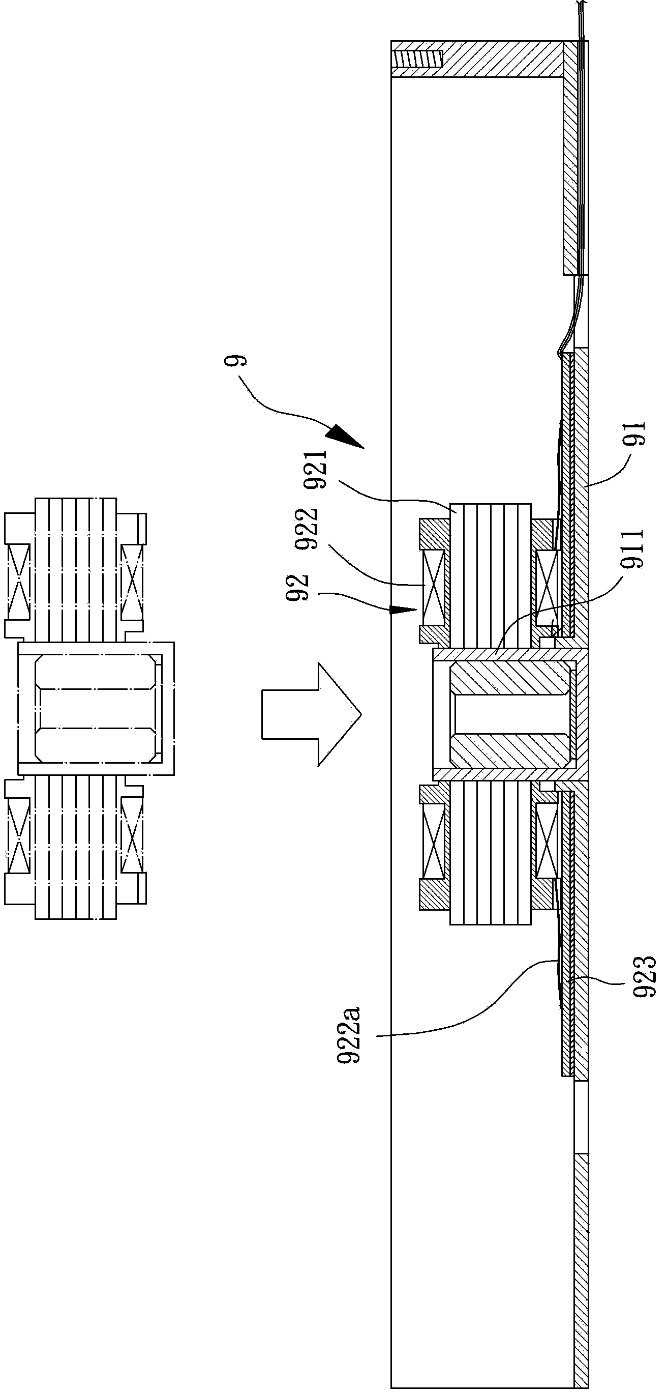
[0005] Or, in order to make the wiring portion 922a of the coil 922 accurately align with the predetermined welding position on the circuit board 923 during welding, some related companies will additionally use various positioning fixtures to position the wiring of the coil 922 before welding. part 922a to facilitate the electrical connection between the coil 922 and the circuit board 923, but when using various positioning fixtures to position the coil 922 during the welding process, it is easy to generate many unnecessary costs, such as: increase The cost of manufacturing and using the positioning jig; and the inconvenience caused by the assembly personnel to use the positioning jig for positioning, resulting in redundant manpower and time costs; or, in the assembly process of a general micro motor, the circuit board 923 is generally After being combined with the base 91 in advance, the welding operation of the wiring portion 922a of the coil 922 is performed, so that the positioning jig must be used in conjunction with the base 91, so the structural design of the positioning jig must consider how to cooperate with the positioning jig. If the base 91 cooperates, there may even be a situation where they cannot cooperate with each other; therefore, the above-mentioned method of using a positioning jig for positioning is actually not in line with economic benefits

Method used


Image

  • Electric connection method for motor stator and coil of motor stator
  • Electric connection method for motor stator and coil of motor stator
  • Electric connection method for motor stator and coil of motor stator

Examples


Embodiment Construction

[0042] In order to make the above and other objects, features and advantages of the present invention more comprehensible, preferred embodiments of the present invention will be described in detail below together with the accompanying drawings.

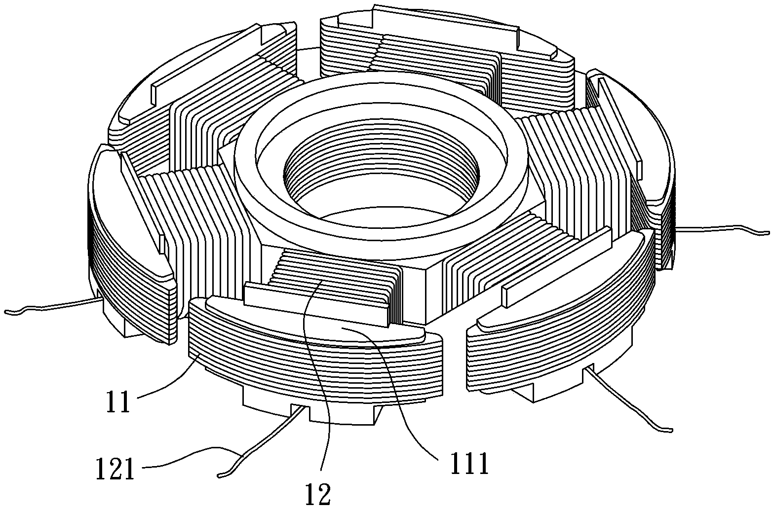
[0043]The electrical connection method of the coil of the motor stator of the preferred embodiment of the present invention comprises the following steps: Please refer to Figure 3a As shown, a core 11 and a coil 12 are prepared. The iron core 11 can be various types of magnetic elements, for example: several silicon steel sheets can be stacked to form a magnetic element, or a single magnetic block can be directly used as the magnetic element; The coil 12 can be an enameled wire, the coil 12 is wound and combined with the core 11, and at least one connection part 121 is pulled out from the coil 12 in advance, and the connection part 121 is a coil section with a predetermined length, so as to carry out the subsequent Coil 12 positioni...


PUM


Abstract

An electric connection method for a motor stator and a coil of the motor stator is used for achieving a good positioning effect during coil welding and comprises the steps that an iron core and the coil are prepared, the coil is combined with the iron core in a wound mode, and at least one wiring part is pulled and led out from the coil in advance; a circuit board is prepared, and a prearranged welding part and an adhesion positioning part are arranged on the circuit board in advance; the wiring part of the coil is positioned on the adhesion positioning part of the circuit board in an adhesive mode, and then the wiring part of the coil is combined with the prearranged welding part of the circuit board in a welded mode so that the coil can be in electric connection with the circuit board through the wiring part. According to the structural design, the circuit board matched with the motor stator is provided with the adhesion positioning part, and therefore the effects of improving the assembly quality of the coil and the circuit board, reducing cost and the like can be achieved.

Description

technical field [0001] The invention relates to a motor stator and its coil electrical connection method, in particular to a method for electrical connection with a circuit board after the coil is pre-positioned, and a motor stator with the coil positioning structure. Background technique [0002] The Chinese patent application No. 201110277390.3 "Cooling fan and assembly method thereof" discloses a conventional motor structure applied to a cooling fan. Please refer to figure 1 , the existing motor 9 roughly includes a base 91 , a motor stator 92 and a motor rotor 93 . The base 91 is provided with a shaft tube 911; the motor stator 92 is combined with the outside of the shaft tube 911, and the motor stator 92 has an iron core 921, a coil 922 and a circuit board 923, and the iron core 921 is used for the coil 922 to be wound Combined, the coil 922 is electrically connected to the circuit board 923; the motor rotor 93 is rotatably combined with the shaft tube 911; thereby, t...

Claims


Application Information

Patent Timeline
IPC IPC(8): H02K3/52
Inventor 王科鑑
Owner SUNON ELECTRONICS KUNSHAN
Learn More