
A construction method for drilling and raising concrete

A construction method and concrete technology, applied in basic structure engineering, basic structure test, construction, etc., can solve the problems of increasing construction cost, wasting manpower and material resources, increasing construction difficulty, etc., and achieve effective construction cost, simple construction, and shortened construction The effect of duration

Active Publication Date: 2016-08-17
HANGZHOU HUANENG SAFETY ENG POLYTRON TECH CO LTD
View PDF6 Cites 0 Cited by
  • Summary
  • Abstract
  • Description
  • Claims
  • Application Information

AI Technical Summary

Problems solved by technology

Existing drilling and raising concrete construction requires crushed stones to mix the concrete, which not only wastes manpower and material resources to transport the crushed stones, but also increases the difficulty of construction and increases the construction cost

Method used


Image

  • A construction method for drilling and raising concrete
  • A construction method for drilling and raising concrete
  • A construction method for drilling and raising concrete

Examples


Embodiment 1

[0110]The parameters of each component mass part per liter of slurry are selected as follows: the mass part of water is 35, the mass part of cement is 75, the mass part of admixture is 60, and the mass part of admixture is 10; after the above test items are tested, the following data are obtained:

[0111]

[0112] The indexes of Example 1 are all within the required indexes, meet the requirements of this construction method, and can be put into use.

Embodiment 2

[0114] The parameters of each component mass part per liter of slurry are selected as follows: the mass part of water is 35, the mass part of cement is 80, the mass part of admixture is 65, and the mass part of admixture is 15; after the test of the above-mentioned test items, the following data are obtained:

[0115]

[0116] Part of the indicators of Example 2 are all within the required indicators, because the larger amount of cement and the stirring time exceed the required indicators, the fluidity of the liter slurry also exceeds the required indicators, which does not meet the requirements of this construction method, and the amount of each component needs to be adjusted before it can be put into use. .

Embodiment 3

[0118] The parameters of each component mass part per liter of slurry are selected as follows: the mass part of water is 35, the mass part of cement is 70, the mass part of admixture is 65, and the mass part of admixture is 15; after the above-mentioned test items are tested, the following data are obtained:

[0119]

[0120] Part of the indexes of Example 3 are all within the required indexes. Because the water volume is relatively large, the density of the liter of slurry is lower than the required index, and the strength of the liter of slurry is also lower than the required index, which does not meet the requirements of this construction method. use.


PUM


Abstract

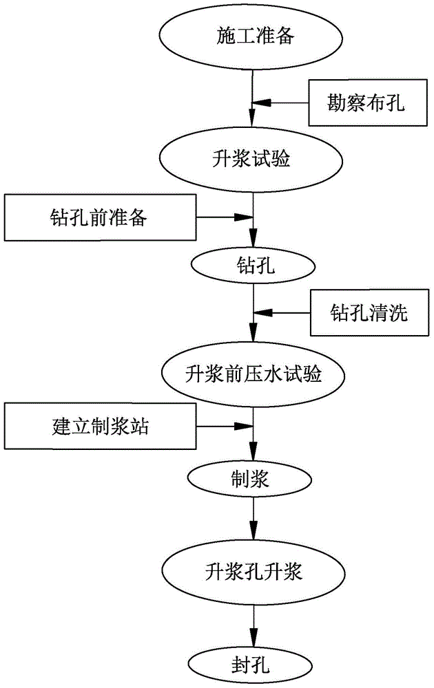
The invention discloses a drilling concrete construction method, which comprises the following steps: (a) preparation for construction; (b) surveying and laying out holes; (c) test for raising slurry; (d) preparation before drilling; (e) drilling ; (f) drilling cleaning; (g) pressure water test before raising the pulp; (h) establishing a pulping station; (i) pulping; (j) raising the pulp hole; (k) sealing the hole. By prefabricating the reserved grouting hole, inserting the grouting pipe into the grouting hole, connecting the grouting pipe to the grouting pipe, the grouting pipe directly injects the grouting liquid into the grouting hole, and then carries out grouting construction, continuous, Uninterrupted grouting. There is no need to crush the stones to mix the concrete; the grout slowly starts upward from the grout hole of the formwork, so all the water in the gaps of the coarse aggregate can be replaced with the grout during underwater construction, and it is easier to produce high-quality concrete; no need The mixer mixes aggregates, which is beneficial to speed up the construction progress; when pumping, only cement mortar is needed, and its pumping process is improved compared with ordinary concrete.

Description

technical field [0001] The invention relates to a construction method for drilling and slurry-raising concrete. Background technique [0002] Construction cofferdams and foundation pits are an important part of dock construction. The construction cost of cofferdam generally accounts for 15% to 20% of the total investment. The technical difficulty is high, the risk is high, and the construction period is also long. It is related to the success or failure, quality and construction period of the project. Its design and construction have always been the focus of industry peers. [0003] In recent years, the use of prefabricated reinforced concrete caisson as the main structure of the cofferdam is generally preferred when building dock projects on the water in rock-based areas. Water-stop construction technologies such as underwater slurry lifting technology and underwater high-pressure rotary jetting have greatly reduced the construction cost of temporary cofferdams and provide...

Claims


Application Information

Patent Timeline
Patent Type & Authority Patents(China)
IPC IPC(8): E02D15/02E02D15/04E02D33/00
Inventor 华勤建彭伟刘学应
Owner HANGZHOU HUANENG SAFETY ENG POLYTRON TECH CO LTD
Learn More