
Power feeder device for slide structure

A technology of sliding structure and power supply device, which is applied in the direction of cable arrangement between relative moving parts, cable installation, electrical components, etc., can solve the problems of space and layout restrictions, power supply structure size, weight and cost increase, etc., to achieve Effects of size reduction, interference prevention, and reliability improvement

Active Publication Date: 2014-11-05
YAZAKI CORP
View PDF8 Cites 8 Cited by
  • Summary
  • Abstract
  • Description
  • Claims
  • Application Information

AI Technical Summary

Problems solved by technology

[0013] However, the conventional power supply device for a sliding structure disclosed in Patent Document 1 has a disadvantage in that since parts such as the housing 82 and the guide rail are provided on the side of the sliding door (that is, the sliding structure) 81, the Space and layout for mounting other components to the sliding door side are limited, and the size, weight and cost of the power supply structure (device) at the sliding door side increase

Method used


Image

  • Power feeder device for slide structure
  • Power feeder device for slide structure
  • Power feeder device for slide structure

Examples


Embodiment Construction

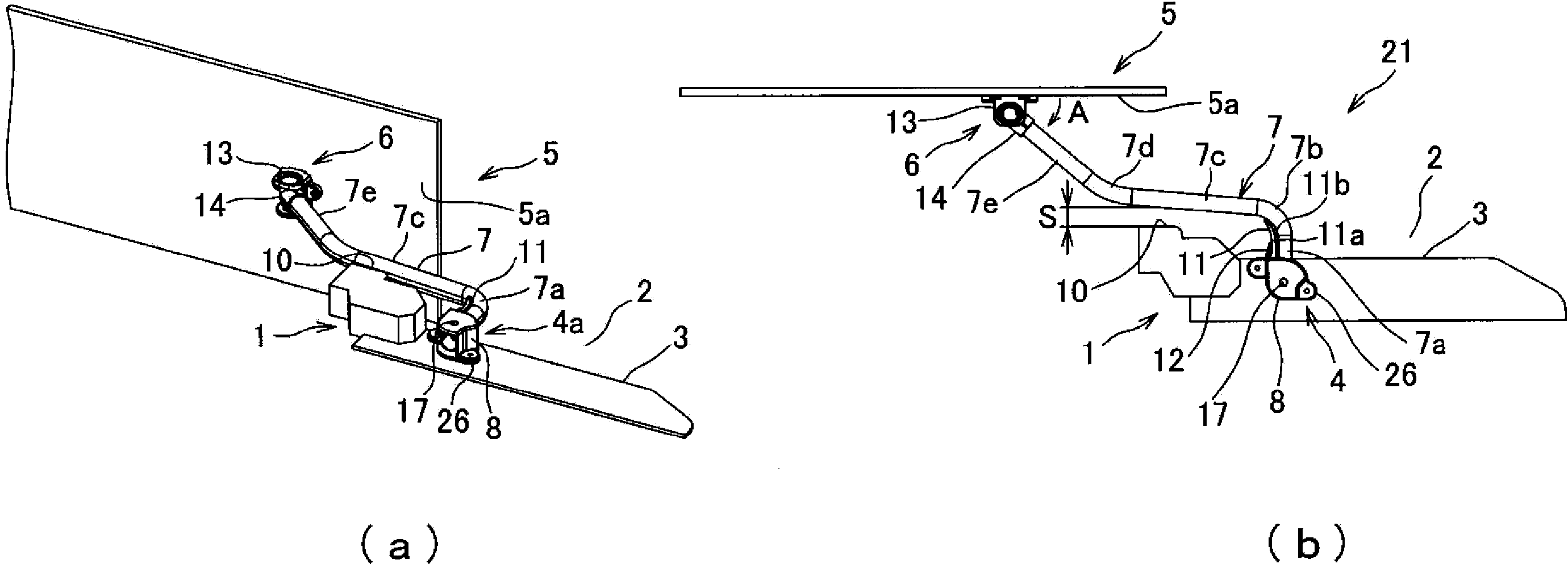
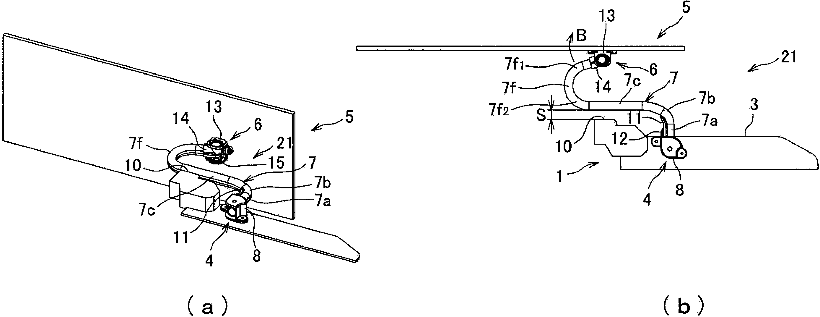
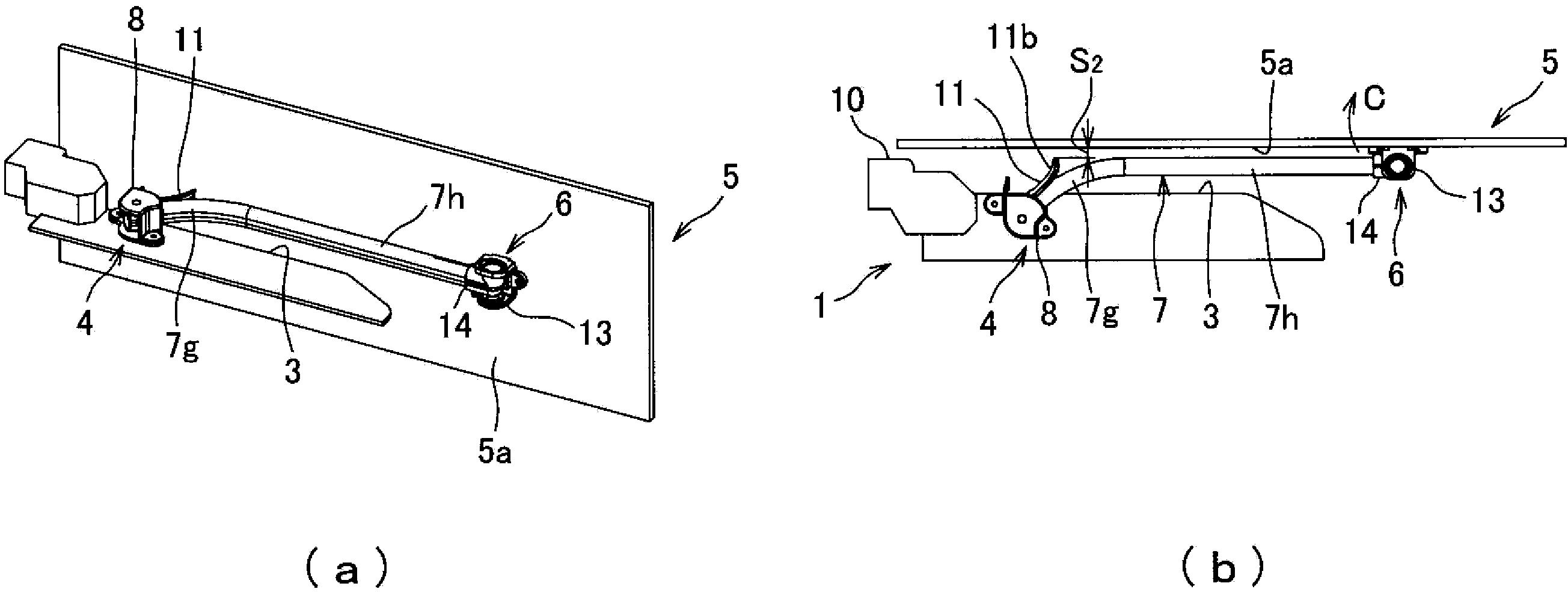
[0077] Figure 1-3 One embodiment of a power supply device for a sliding structure according to the present invention is shown. figure 1 A and 1B show the sliding door (i.e. sliding structure) in a fully open state on the vehicle left side of the car, figure 2 A and 2B show the sliding door in the half-open state, and image 3 A and 3B show the sliding door in the fully closed state.

[0078] Such as figure 1 As shown in A and 1B, the power supply device 21 for the sliding structure includes: a vehicle body side power supply device 4, the vehicle body side power supply device 4 is arranged on the vehicle rear side of the ladder 3 of the entrance 2 of the vehicle body 1, for example; The sliding door side power supply device 6, which is placed on the inner panel 5a made of metal of the sliding door 5, and arranged at the same height as the vehicle body side power supply device 4; and the wiring harness (denoted by reference numeral 7), the wire harness has a corrugated t...


PUM


Abstract

Object is to downsize a sliding structure-side and / or fixed structure-side power supply device and prevent interference between a wiring harness and a fixed structure in a fully-opened state of a sliding structure. A power supply apparatus for sliding structure (21) includes a wiring harness having an exterior member (7) wired from a fixed structure-side power supply device (4) to the sliding structure (5) side, the fixed structure-side power supply device (4) including an outer member (8) fixed to the fixed structure (1), an inner member (9) supported to the outer member so as to rotate in a horizontal direction and configured to support one end portion of the exterior member, and a harness trajectory regulation wall (11) configured to rotate integrally with the inner member. When the sliding structure (5) is fully-opened, the harness trajectory regulation wall (11) projects outward from the outer member in a thickness direction of the sliding structure, such that the exterior member (7) arranged along the harness trajectory regulation wall is moved away from the fixed structure toward the sliding structure side, preventing interference between the exterior member and the fixed structure.

Description

technical field [0001] The present invention relates to a power supply device for a sliding structure including, for example, a swing member for continuously supplying electric power from a body side of an automobile to a sliding door side. Background technique [0002] For example, various power supply devices for sliding structures have been proposed for continuously supplying electric power from a power supply provided on the body side of an automobile to electrical components or accessories provided at a sliding door of the automobile. [0003] For example, Patent Document 1 discloses a Figure 15 The power supply device for the sliding structure shown in A and 15B, the power supply device for the sliding structure is provided with: a housing 82, the housing 82 is vertically arranged at the sliding door 81 of the car; guide rails, the guide rails are arranged in parallel inside the housing; a slider joined to the guide rail so as to slide in the vehicle front-rear direct...

Claims


Application Information

Patent Timeline
IPC IPC(8): H02G11/00B60R16/02
CPCH02G3/0468B60R16/027H02G11/00H02G3/0691
Inventor 池田桂
Owner YAZAKI CORP
Learn More