Photoelectric composite cable

A photoelectric composite cable and cable core technology, which is applied in the direction of insulated cables, communication cables, cables, etc., can solve the problem of large outer diameter of the cable core, and achieve the goals of reducing the outer diameter of the cable core, increasing the strength, and reducing the outer diameter. Effect

Active Publication Date: 2014-11-05
HENAN COMM CABLE +2
View PDF10 Cites 0 Cited by
  • Summary
  • Abstract
  • Description
  • Claims
  • Application Information

AI Technical Summary

Problems solved by technology

[0005] The invention provides a photoelectric composite cable to solve the technical problem in the prior art that the strengthening member in the photoelectric composite cable is arranged in the center of the cable core, resulting in a large outer diameter of the cable core

Method used


Image

  • Photoelectric composite cable

Examples


Embodiment Construction

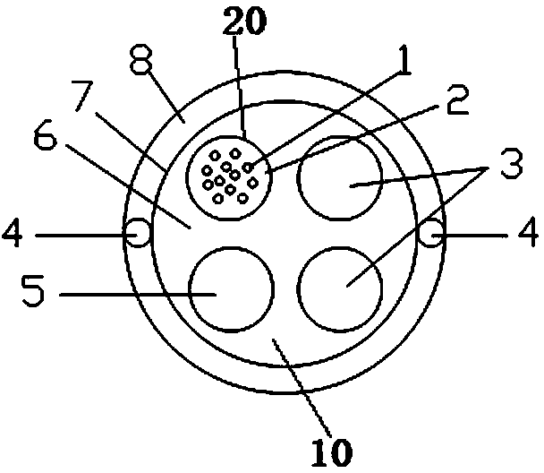
[0018] Such as figure 1 As shown, an embodiment of a photoelectric composite cable, the photoelectric composite cable in this embodiment includes an outer sheath 8 and a cable core 10 arranged in the outer sheath 8, and the cable core 10 includes optical fiber sleeves 20 arranged in parallel at intervals , copper wire 3, filling rope 5 and cable paste 6 filled between the optical fiber sleeve 20, copper wire 3, filling rope 5, wherein two copper wires 3 are provided, the optical fiber sleeve 20, two copper wires 3 and the filling The rope 5 is arranged in the shape of a "field", and the outer sheath 8 is provided with a steel strip longitudinal wrap 7 covering the outer peripheral surface of the cable core 10, and the wall of the outer sheath 8 is provided with the cable core 10 reinforcements 4 extending in parallel. The reinforcements 4 are metal reinforcements that are in contact with the outer peripheral surface of the steel strip longitudinal wrap 7. The metal reinforceme...


PUM


Abstract

The invention provides a photoelectric composite cable which comprises an outer sheath and a cable core arranged in the outer sheath. The cable core comprises an optical fiber bushing, copper conductors, a filler rope and cable paste, wherein the optical fiber bushing, the copper conductors and the filler rope are arranged in a spaced mode; the cable paste is filled among the optical fiber bushing, the copper conductors and the filler rope. A steel belt longitudinal wrap with which the outer circumferential face of the cable core is coated is arranged in the outer sheath, and reinforcers which extend in parallel with the cable core are arranged in the wall of the outer sheath. Compared with the structure that the reinforcers are arranged in the center of the cable core in the prior art, the photoelectric composite cable has the advantages that the reinforcers are arranged in the wall of the outer sheath, the radial dimension of the wall of the outer sheath is effectively utilized, space is not additionally occupied, the outer diameter of the cable core can be effectively reduced on the premise that tensile strength of the composite cable is guaranteed, and accordingly cost of the cable paste filled into the cable core can be lowered and the outer diameter dimension of the whole cable core can be reduced; the cable core is coated with the steel belt longitudinal wrap, so strength of the whole cable core can be effectively improved, and the cable core of the cable can be better protected.

Description

technical field [0001] The invention relates to a photoelectric composite cable. Background technique [0002] In recent years, with the rapid development of communication networks and people's demand for high-speed networks, mobile communications have evolved from analog to digital, from 2G to 4G, and from wireless voice services to wireless multimedia services, thus motivating operators to increase ARPU and develop The new frequency band supports the continuous growth of the number of users, more effective spectrum utilization and lower operating costs, so it has to undergo transformation and transformation. With the massive increase in network construction, higher requirements are put forward for compliant optical cables. [0003] Such as the photoelectric composite cable disclosed in the Chinese invention patent with the authorized announcement number CN201498256U, which includes an outer sheath and a cable core arranged in the outer sheath, and the cable core includ...

Claims


Application Information

Patent Timeline
IPC IPC(8): H01B11/22H01B7/17
Inventor 李建辉马娜娜
Owner HENAN COMM CABLE
Why Eureka
Try Eureka