


Quick Research
Generate reliable direction feasibility study reports for your R&D in just a few steps.

Technical Q&A
Discover and master advanced knowledge NOW. Basics, ideas, possibilities, all at once.

Find Solutions
As an expert in R&D theories, this can generate solutions to your technical problems instantly.

Evaluate Feasibility
Analyze your overall solution with one click, know your potential R&D risks in advance.

Monitor Landscape
Get weekly tech updates, stay abreast of the latest tech innovations and key insights.
A contact thermal resistance detection device under micro-stress conditions
A technology of contact thermal resistance and detection device, applied in the direction of thermal development of materials, can solve the problems of inability to realize the micro-stress contact thermal resistance, the effect of contact stress cannot be eliminated, etc., and achieve the effect of overcoming the influence of friction and accurate detection results.
- Summary
- Abstract
- Description
- Claims
- Application Information
AI Technical Summary
Problems solved by technology
Method used
Image


Examples
specific Embodiment approach 1
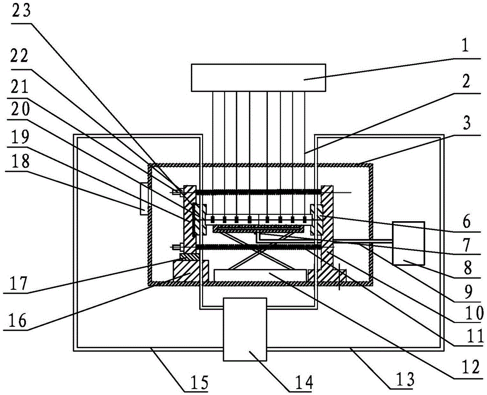
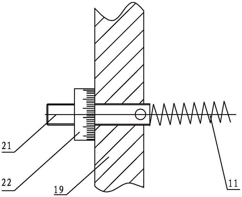
[0020] Specific implementation mode 1. Combination Figure 1-Figure 4 Describe this specific embodiment. A contact thermal resistance detection device under micro-stress conditions described in this specific embodiment includes a vacuum cover 3, a cooling plate 6, a right fixed plate 9, a left fixed plate 19, a support frame 16, and a lifting platform 12 , heating plate 20, screw rod 21, spring 11, nut 22 and insulation plate 23, the inside of described vacuum cover 3 is a vacuum cavity, cooling plate 6, right fixed plate 9, left fixed plate 19, support frame 16, lifting platform 12. The heating plate 20, the screw rod 21 and the spring 11 are all located inside the vacuum chamber, the lift table 12 is fixed on the bottom of the vacuum cover 3, the top of the lift table 12 is placed to be tested, the right fixed plate 9 and the support frame 16 Located on both sides of the lifting platform 12, the right fixed plate 9 and the support frame 16 are all fixed on the bottom of the ...
specific Embodiment approach 2
[0023] Specific embodiment two, combine figure 1 Describe this specific embodiment. The difference between this specific embodiment and the contact thermal resistance detection device under micro-stress conditions described in the first specific embodiment is that it also includes a heat insulating element 17, and the heat insulating element 17 is fixed on the left Between the fixed plate 19 and the support frame 16.
[0024] In this embodiment, the left fixing plate 19 and the support frame 16 are separated by the heat insulating element 17, so that the heat in the heating plate 20 will not be transferred to the vacuum cover 3 through the support frame 16, so that the heat can be concentrated and the detection is improved. precision.
specific Embodiment approach 3
[0025] Specific embodiment three, combine figure 1 Describe this specific embodiment, the difference between this specific embodiment and the contact thermal resistance detection device under micro-stress conditions described in specific embodiment 1 is that it includes a backing plate, a vent pipe 9 and an air pump 8, and the backing plate is fixed On the top of the lifting platform 12, there is an air cavity inside the backing plate, and a plurality of through holes are opened on the top of the backing plate, and the plurality of through holes are all communicated with the air cavity. The air cavity inside the board communicates.
[0026] In this embodiment, when testing the contact thermal resistance of the tested piece, the air between the lifting table 12 and the tested piece is discharged by the air pump 8, thereby overcoming the influence of friction and making the testing result more accurate.
PUM
 Abstract
Description
Claims
Application Information
 - R&D Engineer
- R&D Manager
- IP Professional
- Industry Leading Data Capabilities
- Powerful AI technology
- Patent DNA Extraction
Browse by: Latest US Patents, China's latest patents, Technical Efficacy Thesaurus, Application Domain, Technology Topic, Popular Technical Reports.
© 2024 PatSnap. All rights reserved.Legal|Privacy policy|Modern Slavery Act Transparency Statement|Sitemap|About US| Contact US: help@patsnap.com