Solar sludge constant temperature drying harmless treatment device and method

A harmless treatment and solar energy technology, applied in dehydration/drying/thickened sludge treatment, energy wastewater treatment, combustion methods, etc., can solve the problem of difficult removal of capillary bound water and internal bound water, complex water composition, and large energy consumption and other problems, to achieve the effect of convenient oven temperature control, temperature maintenance and energy saving

Active Publication Date: 2016-06-08
浙江绿治环保技术有限公司
View PDF13 Cites 0 Cited by
  • Summary
  • Abstract
  • Description
  • Claims
  • Application Information

AI Technical Summary

Problems solved by technology

Through research, it is found that the moisture composition in sludge is complex, including interstitial water, surface adsorption water, capillary bound water and internal bound water. Interstitial water and surface adsorbed water are easier to remove and can be treated by mechanical dehydration (such as belt filter press) , centrifugal dehydrator, chamber filter press, etc.), but capillary bound water and internal bound water are difficult to remove, and cannot be removed by mechanical dehydration, and can only be removed by thermal drying or incineration
[0006] The existing thermal drying technology is to burn coal, natural gas or electric heating to generate a large amount of heat to heat the sludge to remove water, but this method will consume a lot of energy during the drying process, and the drying temperature is too high, making the sludge The organic substances in the sludge, especially the release of volatile substances such as benzene, chlorophenol, ammonia, etc., endanger the environment and cause secondary pollution in the process of sludge treatment

Method used


Image

  • Solar sludge constant temperature drying harmless treatment device and method
  • Solar sludge constant temperature drying harmless treatment device and method
  • Solar sludge constant temperature drying harmless treatment device and method

Examples


Embodiment

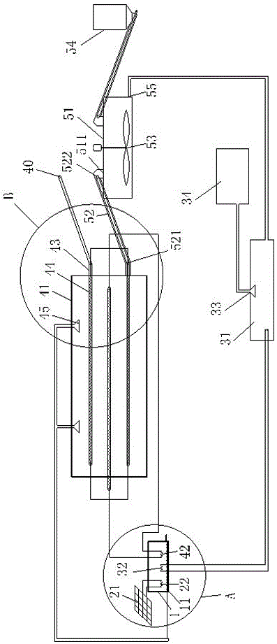
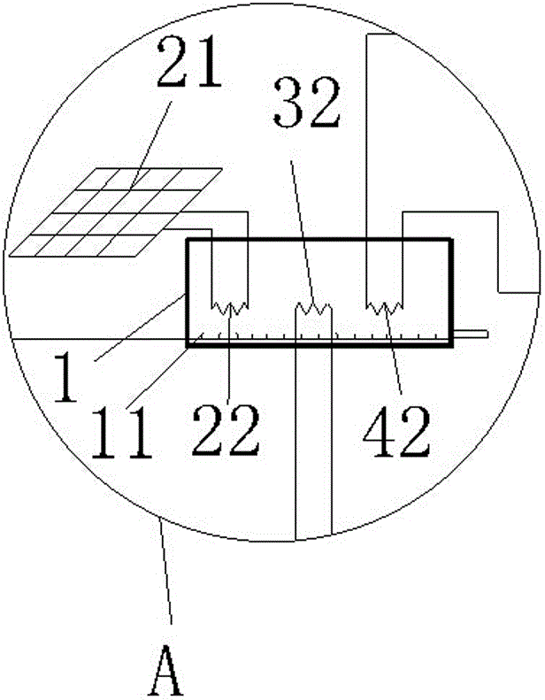
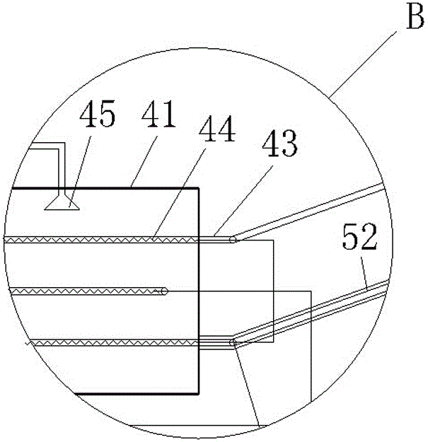
[0030]Solar sludge constant temperature drying and harmless treatment device, including hot water storage pool 1, solar heat collecting device, sludge incineration device, sludge drying device and finished sludge storage device, solar heat collecting device including solar heat collecting plate 21 and solar heat exchanger 22, the sludge incineration device includes an incinerator 31, an incinerator heat exchanger 32, an incineration waste gas collection device 33 and an incineration waste gas treatment device 34, and the sludge drying device includes an oven 41, an oven heat exchanger 42, The oven sludge conveyor belt 43, the heat exchange unit 44 in the oven and the drying exhaust gas collection device 45, the finished sludge storage device includes the finished sludge storage tank 51, the closed sludge conveyor belt 52, the sludge stirring device 53 and the combustion aid Storage tank 54; the solar heat exchanger 22, the incinerator heat exchanger 32 and the oven heat exchang...


PUM


Abstract

The invention discloses a solar sludge constant temperature drying and harmless treatment device and method. The device includes a hot water storage pool, a solar heat collection device, a sludge incineration device, a sludge drying device and a finished sludge storage device. The method includes: step A, collecting solar radiant heat through a solar heat collector, and then transferring the heat into a hot water storage tank; step B, transporting the sludge to be treated into an oven, and collecting the waste gas generated by drying through the drying waste gas The device collects and sends it to the hot water storage tank through the pipeline, and the soluble gas in the waste gas is dissolved in the water through aeration; step C, the sludge is dried and transported into the finished sludge storage tank in a closed manner, and a combustion aid is added to carry out Stirring; step D, after stirring evenly, the sludge is sent to the incinerator for combustion, which can provide heat for the hot water storage pool, and the remaining waste residue after combustion can be used as building materials for resource disposal. The invention truly realizes the goals of reduction, harmlessness and resource utilization of sludge treatment.

Description

technical field [0001] The invention relates to a device and a method for treating sludge generated in a sewage treatment plant. Background technique [0002] With the popularization of urban sewage treatment, the sludge produced by urban sewage treatment plants has increased a lot. Due to the characteristics of high moisture content, large volume, easy pollution, and complex composition of sludge, it is easy to cause problems in stacking, transportation, storage, and utilization. Many troubles have come, and various problems caused by sludge treatment have attracted more and more people's attention. [0003] The common characteristics of sludge are high water content, large volume, difficult to handle, complex components, containing a large amount of organic substances, toxic and harmful heavy metals, pathogenic microorganisms, parasite eggs, salts and radionuclides and other refractory substances. [0004] The most critical indicator of sludge treatment is the water conte...

Claims


Application Information

Patent Timeline
Patent Type & Authority Patents(China)
IPC IPC(8): C02F11/12F23G7/00
CPCY02W10/37
Inventor 汪荣青曹黎任炜刘岗包宇鼎
Owner 浙江绿治环保技术有限公司
Why Eureka
Try Eureka