
V-block-positioning pneumatic clamping machining center fixture

A machining center and pneumatic clamping technology, applied in positioning devices, clamping devices, manufacturing tools, etc., can solve the problems of low processing efficiency, difficult to guarantee workpiece processing accuracy, long time for workpiece alignment, etc., to achieve stable processing, structure Simple, novel, and easy-to-operate effects

Inactive Publication Date: 2014-11-05
ANHUI TECHN COLLEGE OF MECHANICAL & ELECTRICAL ENG
View PDF8 Cites 33 Cited by
  • Summary
  • Abstract
  • Description
  • Claims
  • Application Information

AI Technical Summary

Problems solved by technology

[0002] With the development of product manufacturing and production to mass customization and batch mode, in the field of modern mechanical numerical control machining, it is often encountered that the surface of the workpiece and its upper holes, grooves and other processes are intensively processed, and ordinary fixtures are unstable when clamping and aligning. Moreover, it takes a long time to align the workpiece, the machining accuracy of the workpiece is difficult to guarantee, and the processing efficiency is low

Method used


Image

  • V-block-positioning pneumatic clamping machining center fixture
  • V-block-positioning pneumatic clamping machining center fixture
  • V-block-positioning pneumatic clamping machining center fixture

Examples


Embodiment Construction

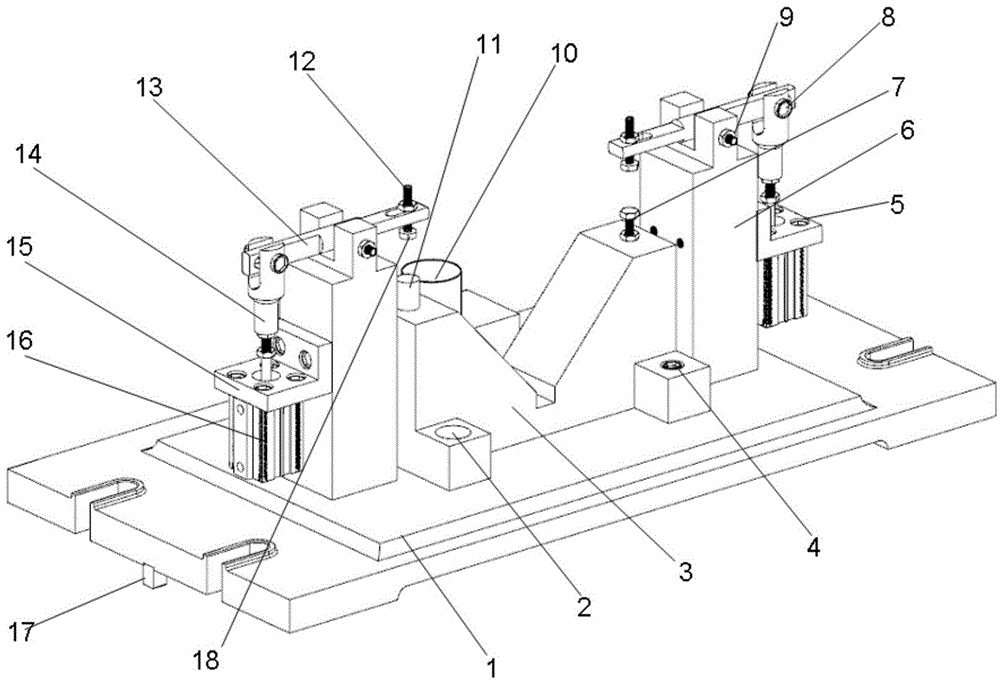
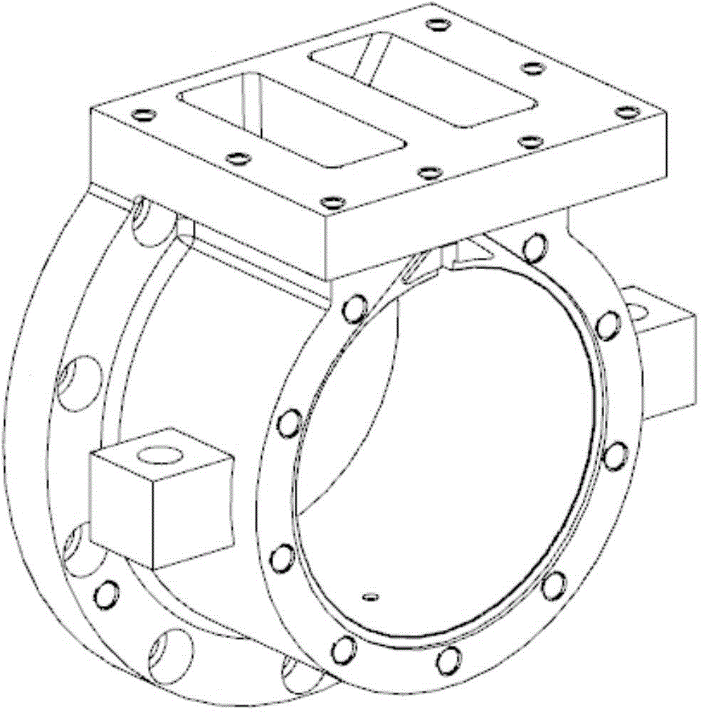
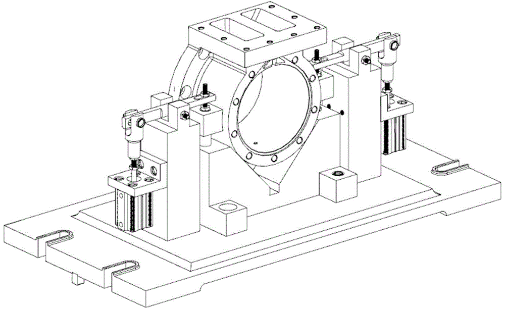
[0023] Such as Figure 1~Figure 5 As shown, a pneumatic clamping machining center fixture with V-shaped block positioning includes a clamp body 1, a positioning mechanism and a clamping mechanism. The positioning mechanism includes a V-shaped block 3, which is fixed on the clamp body 1, and the V-shaped block 3 is fixed on the clamp body 1. A fixed support 11 and an auxiliary support 7 are respectively fixed on the upper end surfaces of both ends of the block 3, and a cylindrical stop pin 10 is provided on the side corresponding to the center of the V port of the V-shaped block 3; Cylinders 16 on both sides of the block 3, a column 6 is respectively arranged between the two cylinders 16 and the V-shaped block 3, and the bottoms of the two columns 6 are fixed on the clamp body 1, and the ejector rods 14 of the two cylinders 16 are vertically arranged, and the ejector rods The top of 14 is horizontally rotated to be equipped with lever 13, and the middle part of lever 13 is rota...


PUM


Abstract

The invention discloses a V-block-positioning pneumatic clamping machining center fixture comprising a fixture body, a positioning mechanism and a clamping mechanism. The positioning mechanism comprises a V-block fixed on the fixture body, a fixed support and an auxiliary support are fixed on the upper end faces of two ends of the V-block respectively, and a cylindrical stop pin is arranged on one side corresponding to the center of a V-opening of the V-block. The clamping mechanism comprises two cylinders respectively located on two sides of the V-block, a column is arranged between each cylinder and the V-block, the bottoms of the two columns are fixed on the fixture body, push rods of the cylinders are arranged vertically, a lever is mounted on the top of each push rod transversely and rotationally, the middle of each lever is rotationally mounted at the top of the corresponding column, the other end of each lever is fixed with a pressing block, and each pressing block is located on the lower end face of the corresponding lever and located over the fixing support or the auxiliary support. The V-block-positioning pneumatic clamping machining center fixture is quick and accurate in positioning, quick, controllable and reliable in clamping, and capable of guaranteeing machining stability.

Description

technical field [0001] The invention relates to the technical field of fixture design for numerical control machine tools, in particular to a pneumatic clamping machining center fixture with V-shaped block positioning. Background technique [0002] With the development of product manufacturing and production to mass customization and batch mode, in the field of modern mechanical numerical control machining, it is often encountered that the surface of the workpiece and its upper holes, grooves and other processes are intensively processed, and ordinary fixtures are unstable when clamping and aligning. Moreover, it takes a long time to align the workpiece, the machining accuracy of the workpiece is difficult to guarantee and the machining efficiency is low. Considering that fast clamping can improve production efficiency, in view of the process concentration requirements of machining center machine tools, if a variety of series of special fixtures are designed, the production...

Claims


Application Information

Patent Timeline
IPC IPC(8): B23Q3/08
CPCB23Q3/08B23Q2703/04
Inventor 张国政李嘉翔杨磊
Owner ANHUI TECHN COLLEGE OF MECHANICAL & ELECTRICAL ENG
Learn More