Clamp for slow wire feeding machine tool

A technology of slow wire walking and machine tools, applied in clamping, manufacturing tools, metal processing machinery parts, etc., can solve the problems of complex fixture structure and narrow application range, achieve simple fixture structure, reduce surface damage, reduce excessive large deformation effect

Inactive Publication Date: 2014-11-05
SHANGHAI UNIV OF ENG SCI
View PDF7 Cites 4 Cited by
  • Summary
  • Abstract
  • Description
  • Claims
  • Application Information

AI Technical Summary

Problems solved by technology

This patent solves the problem of clamping, but the structure of the clamp is relatively complicated and the scope of use is narrow

Method used


Image

  • Clamp for slow wire feeding machine tool
  • Clamp for slow wire feeding machine tool
  • Clamp for slow wire feeding machine tool

Examples


Embodiment

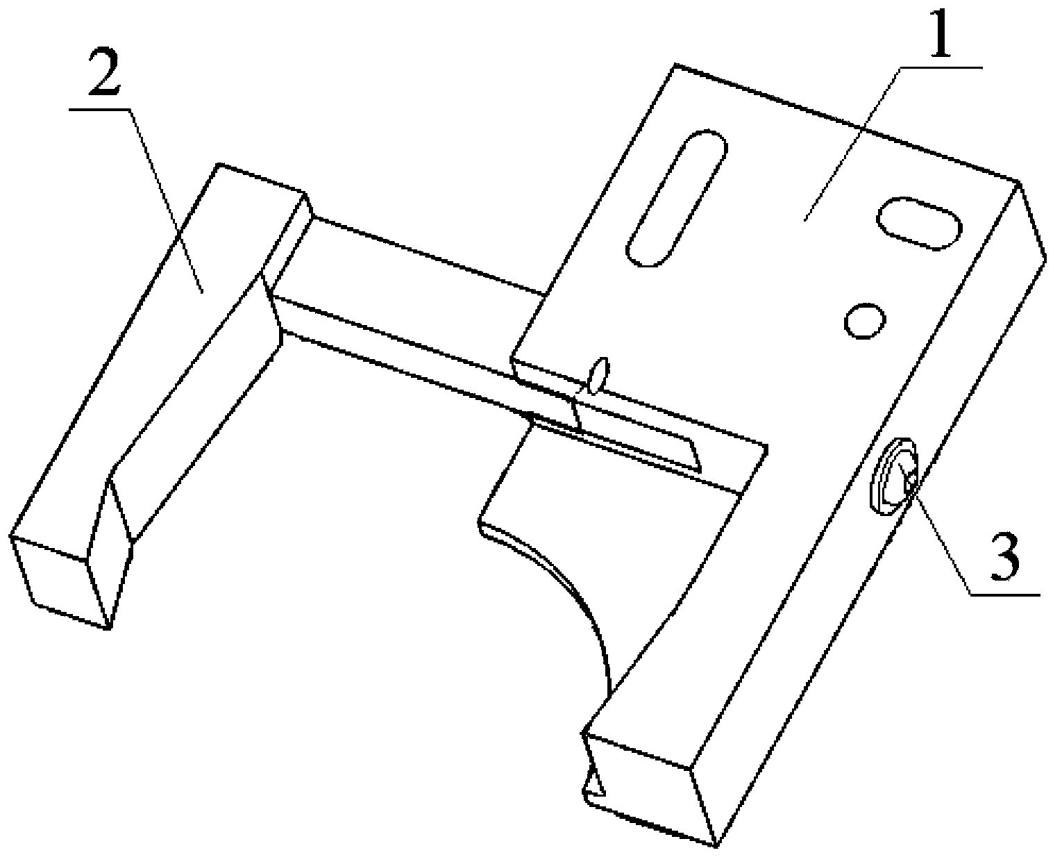
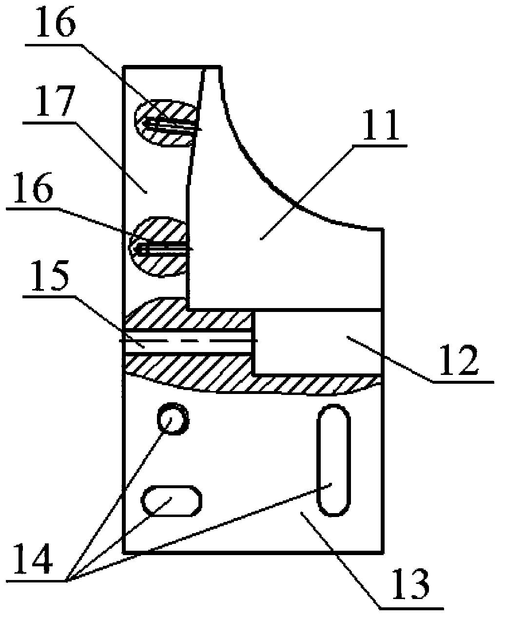
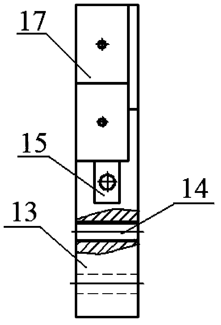
[0027] A fixture used on slow wire machine tools, such as figure 1 As shown, it includes fixed claw 1 and movable claw 2. Fixed claw 1 such as figure 2 , image 3 As shown, the fixed claw 1 includes a support plate 11 for supporting the workpiece, a first clamping arm 17 provided on the support plate 11, and a fixed arm 13 integrally provided with the first clamping arm 17. The fixed arm 13 is provided with There is a guide groove 12, the rear side of the guide groove 12 is provided with a through hole 15, and the bolt 3 is arranged in the through hole 15. The structure of movable claw 2 is as Figure 4 , Figure 5 As shown, the movable claw 2 includes a second clamping arm 21 and a sliding arm 22 connected with the second clamping arm 21. The sliding arm 22 is inserted in the guide groove 12 and connected with the bolt 3 arranged in the through hole 15. The sliding arm 22 is provided with a bolt hole 23 threadedly connected with the bolt 3. By rotating the bolt 3, the s...


PUM


Abstract

The invention relates to a clamp for a slow wire feeding machine tool. The clamp comprises a fixed jaw and a movable jaw, the fixed jaw comprises a supporting plate for supporting a workpiece, a first clamping arm arranged on the supporting plate and a fixed arm, the fixed arm and the first clamping arm are integrally arranged, a guide groove is formed in the fixed arm, a through hole is formed in the rear side of the guide groove, and a bolt is arranged in the through hole. The movable jaw comprises a second clamping arm and a sliding arm connected with the second clamping arm, the sliding arm is inserted in the guide groove, and is connected with the bolt in the through hole, the sliding arm slides in the guide groove by rotating the bolt, and the second clamping arm is close to the first clamping arm and clamps the workpiece. Compared with the prior art, the clamp has the advantages of being simple in structure, convenient to use, wide in use range, small in damage to the surface of the workpiece and the like.

Description

technical field [0001] The invention relates to a clamp, in particular to a clamp used on a slow-moving wire machine tool. Background technique [0002] During the use of slow-moving wire machine tools, it is sometimes necessary to process round or similar round workpieces, so it is necessary to have a fixture that can hold such workpieces. At present, the general fixtures on the market adopt the method of direct docking of two V-shaped blocks, and use the friction force and centering force generated by the clamping force between the V-shaped blocks and the workpiece to clamp the workpiece. This kind of fixture can be used for Clamp most round or similar round workpieces, but when encountering large workpieces or workpieces with high mass, due to the large friction force required, the V-shaped block is required to exert a large force on the workpiece during the clamping process. If the clamping force is too high, it will easily cause excessive deformation or surface damage ...

Claims


Application Information

Patent Timeline
Patent Type & Authority Applications(China)
IPC IPC(8): B23Q3/06
CPCB23H11/003B23H7/02
Inventor 王克用刘博陈钧陈俊曲贺李军
Owner SHANGHAI UNIV OF ENG SCI
Why Eureka
Try Eureka