Hydraulic Separation Device and Separation Process for Hot Formed Steel Plate

A separation device and thermoforming technology, which is applied in the field of hydraulic separation device and separation process, can solve the problems of high maintenance frequency, noise mold wear, and high cost of laser cutting process, so as to reduce investment and use requirements, solve large vibration and noise, The effect of improving quality stability

Active Publication Date: 2016-08-24
WUXI LANGXIAN LIGHTWEIGHT TECH CO LTD +1
View PDF7 Cites 0 Cited by
  • Summary
  • Abstract
  • Description
  • Claims
  • Application Information

AI Technical Summary

Problems solved by technology

[0003] For the separation of hot-formed steel plates, if the traditional press control stamping die separation process for ordinary steel plates and ordinary high-strength steel plates is used, as disclosed in Chinese patent CN102189179A "a car stamping die with automatic trimming and shaping And its stamping process" in the mold structure, the edge trimming punch and the edge of the trimming die are consistent with the shape of the workpiece, and the separation process can be completed instantly at a certain speed within one stroke. When the stamping is separated, the edge trimming The die and the workpiece are in line contact. Due to the high strength and high brittleness of the hot-formed steel plate, the stamping force is huge at the moment of stamping, which requires a large-tonnage press. Taking the body-in-white parts of the automotive industry as an example, it usually requires about 1,000 tons On the other hand, due to the instant completion of the separation process at a certain speed, the impact force at the moment of stamping is huge, the die is worn seriously, and the maintenance frequency is high. At the same time, in order to buffer, the press must be equipped with Cushion pads, even so, are still difficult to solve the problems of noise and mold wear caused by instantaneous huge changes in pressure. Therefore, most of the existing separation processes (including trimming and punching) of high-strength steel hot-formed steel plates use laser cutting processes
However, the laser cutting process requires the use of a laser cutting head, and a corresponding drive and transmission mechanism must be provided for each degree of freedom of the laser cutting head, such as the "laser cutting machine" disclosed in Chinese patent CN201483157U, whose cutting efficiency is limited The movement speed of the laser cutting head, compared with the traditional press with the separation device of the mold, the laser cutting process not only has high cost, but also has low work efficiency

Method used


Image

  • Hydraulic Separation Device and Separation Process for Hot Formed Steel Plate
  • Hydraulic Separation Device and Separation Process for Hot Formed Steel Plate
  • Hydraulic Separation Device and Separation Process for Hot Formed Steel Plate

Examples


Embodiment 1

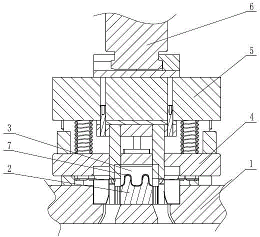
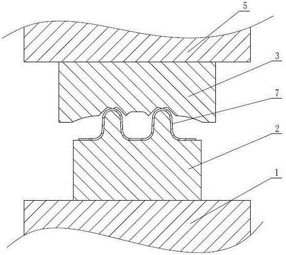
[0055] This embodiment is a preferred embodiment of the present invention. The hydraulic separation device uses a hydraulic system 6 with a tonnage of 60 tons, and does not need to be equipped with a buffer pad. The pressure is adjustable within the range of 0-60 tons, and the speed is 0-450mm / s Adjustable, the stroke of the dynamic separation insert 3 is 300mm, the stroke of the pressing block 4 is 30mm, and the pressing force is 4 tons. In terms of specific material selection, the dynamic separation insert 3 and the static separation insert 2 The cutting edge material can be SKD61, CALDIE, V4E and other high-quality mold steel with a hardness of HRC50 and above and toughness, and the hardness of the static separation insert 2 should not exceed the hardness of the dynamic separation insert 3. The specific separation process is as follows:

[0056] The first step, workpiece delivery: quickly place the workpiece 7 on the static separation insert 2 within 0.5 seconds;

[0057] I...

Embodiment 2

[0063] The hydraulic separation device described in this embodiment uses a hydraulic system 6 with a tonnage of 60 tons, and does not need to be equipped with a cushion. The stroke of 3 is 300mm, the stroke of pressing block 4 is 30mm, and the pressing force is 4 tons. In terms of specific material selection, the cutting edge materials of the dynamic separation insert 3 and the static separation insert 2 can be SKD61, CALDIE , V4E and other high-quality mold steels with a hardness of HRC50 and above and toughness, and control the hardness of the static separation insert 2 not to exceed the hardness of the dynamic separation insert 3. The specific separation process is as follows:

[0064] The first step, workpiece delivery: quickly place the workpiece 7 on the static separation insert 2 within 0.5 seconds;

[0065] In the second step, the hydraulic system 6 drives the slider 5 to move rapidly towards the static separation insert 2 at a maximum speed of 150mm / s, and the pressin...

Embodiment 3

[0071] The hydraulic separation device described in this embodiment uses a hydraulic system 6 with a tonnage of 60 tons, and does not need to be equipped with a cushion. The stroke of 3 is 300mm, the stroke of pressing block 4 is 30mm, and the pressing force is 4 tons. In terms of specific material selection, the cutting edge materials of the dynamic separation insert 3 and the static separation insert 2 can be SKD61, CALDIE , V4E and other high-quality mold steels with a hardness of HRC50 and above and toughness, and control the hardness of the static separation insert 2 not to exceed the hardness of the dynamic separation insert 3. The specific separation process is as follows:

[0072] The first step, workpiece delivery: quickly place the workpiece 7 on the static separation insert 2 within 0.5 seconds;

[0073] In the second step, the hydraulic system 6 drives the slider 5 to move quickly towards the static separation insert 2 at a maximum speed of 900mm / s, and the pressin...


PUM


Abstract

The hydraulic separation device for hot-formed steel plates includes a worktable and a static separation insert fixed on the worktable. The workpiece is positioned on the static separation insert, and the dynamic separation insert is located above the static separation insert. On the block, the binder block is elastically connected to the slider, and the hydraulic system drives the slider to move relative to the static separation insert. The cutting edge profile of the static separation insert is consistent with the surface shape of the workpiece, and the hardness of the dynamic separation insert is greater than or equal to the static separation Separate the hardness of the insert, and the hardness of the two should be at least HRC50 and have toughness. The invention also provides a corresponding separation process, which mainly adopts low-speed separation and edge point contact separation for high-strength hot-formed steel plates. The invention is suitable for the separation operation of hot-formed steel plates. While ensuring the separation efficiency, it can greatly reduce the impact on the separation device during separation, reduce the wear of the separation device, prolong the service life of the separation device, and greatly reduce the separation rate. the required force.

Description

technical field [0001] The invention relates to the technical field of separation of hot-formed steel plates, in particular to a hydraulic separation device and separation process for trimming and / or punching high-strength and ultra-high-strength steel plates after hot-forming treatment. Background technique [0002] High-strength steel plate has high strength, especially in the state of normalizing or normalizing plus tempering, it has high comprehensive mechanical properties. The application of high-strength steel plate is an effective means to ensure light weight and collision safety at the same time. , Power station equipment, medium and high pressure boilers, high pressure vessels, rolling stock, lifting machinery and other engineering industries are widely used. As a new thing, hot-formed steel plate is different from ordinary high-strength steel plate in its production process. The production process of hot-formed steel plate usually includes two stages of forming and...

Claims


Application Information

Patent Timeline
Patent Type & Authority Patents(China)
IPC IPC(8): B21D28/02B21D28/24
Inventor 陈扬
Owner WUXI LANGXIAN LIGHTWEIGHT TECH CO LTD
Why Eureka
Try Eureka