
Spittoon Rotation Mechanism for Dental Units

A technology of a rotating mechanism and a treatment machine, applied in dentistry, medical science, cleaning teeth, etc., can solve the problems of inconvenient operation, irreversibility, and inability to realize manual rotation at the same time by doctors, and achieve the effect of protecting equipment safety and realizing manual rotation.

Active Publication Date: 2015-12-23
SINOL MEDICAL EQUIP GRP CO LTD
View PDF9 Cites 0 Cited by
  • Summary
  • Abstract
  • Description
  • Claims
  • Application Information

AI Technical Summary

Problems solved by technology

The purpose of spittoon rotation is to obtain a better spit position for patients or a larger operating space for medical staff during oral treatment. The spittoon rotation mechanism of traditional dental comprehensive treatment machines usually adopts two rotation methods: one is manual Rotation, using a shaft sleeve to cooperate, the shaft is firmly connected with the spittoon, the sleeve is a fixed seat, and the position of the spittoon can be manually rotated to adjust; the second is automatic rotation, powered by a motor, and the rotation motion is transmitted to the terminal through gears or other transmission mechanisms to achieve The rotation of the terminal, when the power is transmitted by gears or other transmission mechanisms, when the deceleration is relatively large, the transmission is irreversible. If the automatic rotation is realized, the manual rotation cannot be realized at the same time. If the automatic rotation terminal is blocked, the equipment will be damaged.
The above-mentioned defects bring great inconvenience to the doctor's operation, so it is necessary to propose an improvement

Method used


Image

  • Spittoon Rotation Mechanism for Dental Units
  • Spittoon Rotation Mechanism for Dental Units

Examples


Embodiment Construction

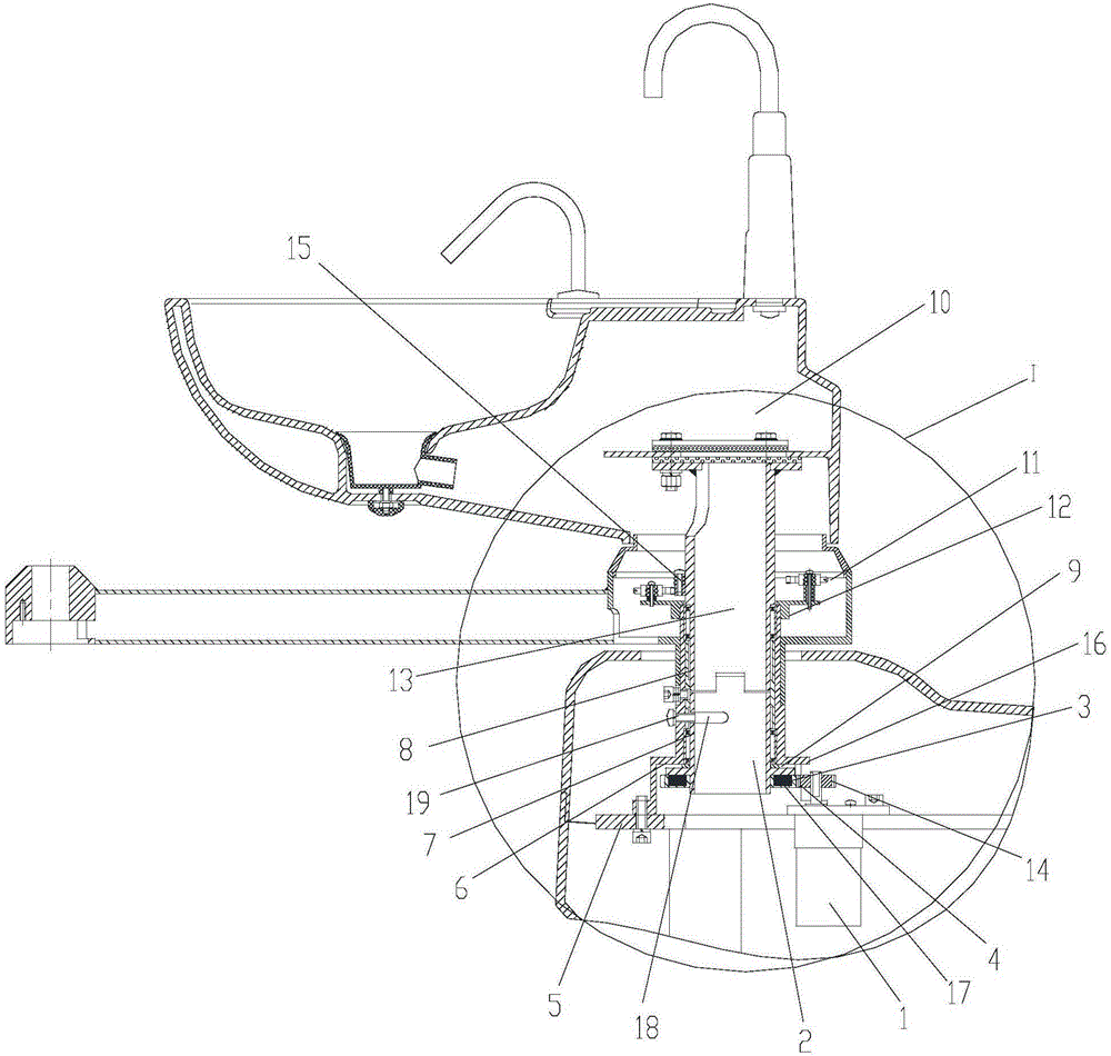
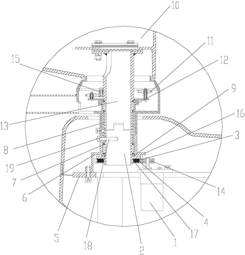
[0014] Attached below figure 1 , 2 An embodiment of the present invention is described.

[0015] The spittoon rotating mechanism used for dental treatment machines has a spittoon motor 1 and a support base 6 fixed on the top plate 5 of the box body, the output shaft of the spittoon motor 1 is provided with a pinion 14, the upper end of the transmission shaft 2 and the lower end of the spittoon shaft 13 After the connection, they are jointly supported in the support seat 6 through the bearing 7. The upper end surface of the convex ring 16 is provided with a washer 9, and the outer ring of the bearing 7 is against the washer 9. There are two bearings 7, and between the bearings 7 A bushing 8 is provided, wherein the upper part of the spittoon rotating shaft 13 protrudes from the support seat 6 and the outer circumference of the upper part of the support seat 6 is provided with two limit switches 11 at an angle of 90 degrees. The cam 15 that touches the limit switch 11 when the...


PUM


Abstract

The invention provides a rotary mechanism of a spittoon for a dental unit. The mechanism is provided with a spittoon motor and a supporting base which are fixedly arranged on a top plate of a box body, wherein a pinion is arranged on an output shaft of the spittoon motor, the upper end of a transmission shaft and the lower end of a rotary shaft of the spittoon are connected and then jointly supported in the supporting base by virtue of a bearing, the upper part of the rotary shaft of the spittoon extends out of the supporting base and two limiting switches with an included angle of 90 degrees are arranged on the outer circumference of the upper part of the supporting base, a cam which is contacted with the limiting switches when the rotary shaft of the spittoon rotates is arranged on the part, which is exposed out of the supporting base, of the rotary shaft of the spittoon, a rack wheel engaged with the pinion is adsorbed at the lower end of the transmission shaft by virtue of a magnet, and the upper end of the rotary shaft of the spittoon is fixedly connected with the spittoon. According to the mechanism provided by the invention, by means of dynamic drive and magnetic absorption effect between the rack wheel and the transmission shaft, the transmission motor rotates to realize self-rotation of the spittoon or transmission is disabled by means of a slip phenomenon between the rack wheel and the transmission shaft, so that manual rotation is realized and the equipment safety is protected.

Description

technical field [0001] The invention belongs to the technical field of medical instrument rotating devices, and in particular relates to a spittoon rotating mechanism for dental treatment machines. Background technique [0002] Dental comprehensive treatment machine is usually used for the examination and treatment of oral diseases, and it is the main diagnosis and treatment equipment of stomatology. The comprehensive dental treatment machine is mainly composed of the main box, spittoon, instrument arm, instrument tray, assistant frame, dental light and supporting dental chair. The purpose of spittoon rotation is to obtain a better spit position for patients or a larger operating space for medical staff during oral treatment. The spittoon rotation mechanism of traditional dental comprehensive treatment machines usually adopts two rotation methods: one is manual Rotation, using a shaft sleeve to cooperate, the shaft is firmly connected with the spittoon, the sleeve is a fixe...

Claims


Application Information

Patent Timeline
Patent Type & Authority Patents(China)
IPC IPC(8): A61C17/14
Inventor 姚卫民聂西社
Owner SINOL MEDICAL EQUIP GRP CO LTD
Learn More