Cannula device for fixing curettage instrument
A technique for surgical instruments and cannula devices, applied in the field of medical instruments, can solve the problems that the instruments are not easy to reach the surgical site, difficult to apply force, increase bleeding and infection, etc., and achieve the effects of reducing uterine infection, avoiding pollution, and alleviating pain.
- Summary
- Abstract
- Description
- Claims
- Application Information
AI Technical Summary
Problems solved by technology
Method used
Image
Examples
Embodiment 1
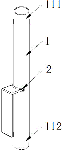
[0046] In this embodiment, the present invention is realized through the following technical solutions: including a sleeve body 1 and a connecting device 2; the connecting device 2 is detachably connected to the cervical forceps; the sleeve body 1 is a hollow sleeve, including a front end 111 and a rear end 112; the front end 111 is connected with surgical instruments that can enter the body for operation; the rear end 112 is away from the surgical operation end.
[0047] During the curettage operation, the surgeon holds the cervical forceps holding the cervix in the whole process, and the bottom of the repeatedly used surgical instrument is socketed with the sleeve body 1 . When the surgical instrument is idle, the connection device 2 on the sleeve body 1 is connected, and the sleeve body 1 and the surgical instrument are vertically hung on the side of the cervical forceps; the operating end of the surgical instrument is upward, and the grip end is downward; the surgical instr...
Embodiment 2
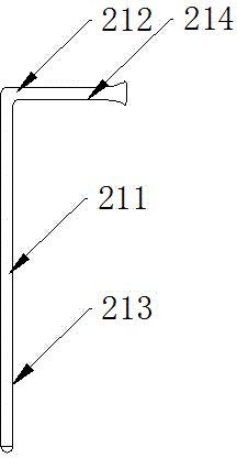
[0049] This embodiment is further optimized on the basis of the above embodiments, further, as figure 1 As shown, the sleeve body 1 is connected to the human flow suction tube; the connecting device 2 is an inverted L-shaped hook arranged on the outer surface of the sleeve body 1; the inverted L-shaped hook and cervical forceps are detachable Buckle connection; the inverted L-shaped buckle includes a long side 211, a short side 212, a first contact surface 213 and a second contact surface 214; the first contact surface 213 is the contact between the inner side of the long side 211 and the cervical forceps The second contact surface 214 is the contact surface between the inner side of the short side 212 and the back of the cervical forceps; the front end 111 is connected to the flow suction tube; the rear end 112 is connected to the disposable suction hose. During the operation, the flow suction tube, the cannula body 1, the disposable hose suction tube, and the negative pressu...
Embodiment 3
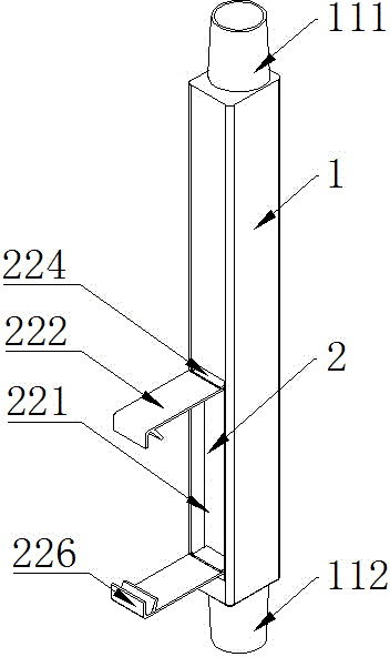
[0053] This embodiment is further optimized on the basis of the above embodiments, further, as image 3 As shown, the sleeve body 1 is connected to the human flow suction tube; the connecting device 2 is a buckle device arranged on the outer surface of the sleeve body 1; connection; the buckle device includes a clip 222, a rotating pin 223, a bracket 224 and a storage groove 221; one end of the clip 222 is provided with two symmetrical lug holes 225, and the other end is provided with a trapezoidal claw 226; the storage The bottom of the slot 221 is provided with a bracket 224; the end of the bracket 224 is provided with a through hole 227; the rotating pin 223 is connected to the lug hole 225 through the through hole 227; the rotating pin 223 is a spring pin, including a tubular cylinder, a set Two cylindrical parts 228 at the ends of the cylinder and a compression spring 229 arranged in the tubular cylinder; the front end 111 is connected with the flow suction tube; the rear...
PUM
 Abstract
Description
Claims
Application Information
 - Generate Ideas
- Intellectual Property
- Life Sciences
- Materials
- Tech Scout
- Unparalleled Data Quality
- Higher Quality Content
- 60% Fewer Hallucinations
Browse by: Latest US Patents, China's latest patents, Technical Efficacy Thesaurus, Application Domain, Technology Topic, Popular Technical Reports.
© 2025 PatSnap. All rights reserved.Legal|Privacy policy|Modern Slavery Act Transparency Statement|Sitemap|About US| Contact US: help@patsnap.com


