Organic light-emitting device and preparation method thereof
An electroluminescent device and electroluminescent technology, which are applied in the fields of electro-solid devices, semiconductor/solid-state device manufacturing, electrical components, etc. problem, to achieve the effect of improving stability, good stability, and improving luminous efficiency
- Summary
- Abstract
- Description
- Claims
- Application Information
AI Technical Summary
Problems solved by technology
Method used
Image
Examples
Embodiment 1
[0079] A method for preparing an organic electroluminescent device, comprising the following steps:
[0080] (1) Ultrasonic cleaning of the ITO glass substrate with detergent and deionized water for 15 minutes each to obtain a clean conductive anode glass substrate;
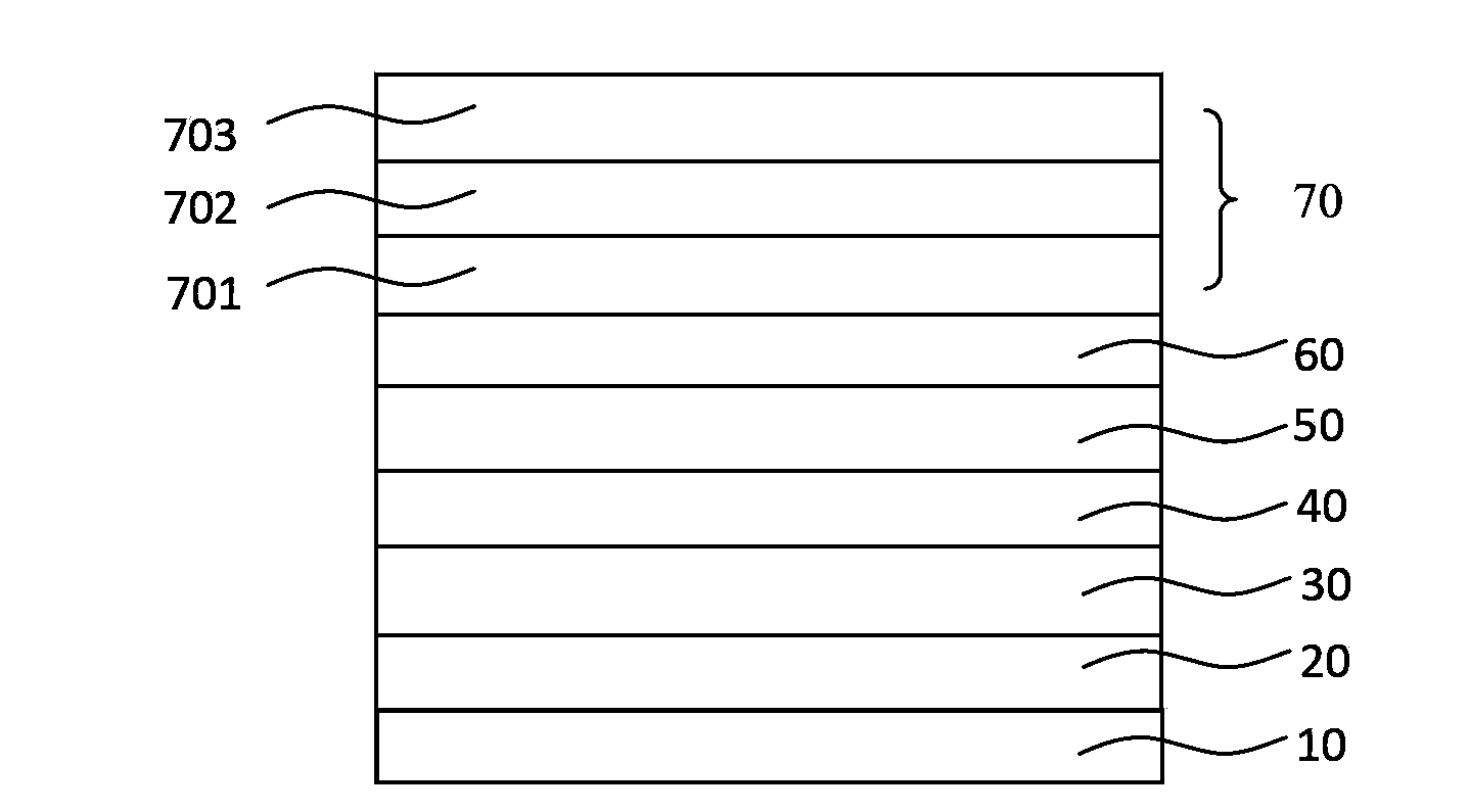
[0081] (2) In the high vacuum coating system (Shenyang Scientific Instrument Development Center Co., Ltd.), the pressure is 8×10 -5 Under the condition of Pa, on a clean conductive anode glass substrate, thermally resistively evaporated hole injection layer, hole transport layer, light emitting layer, electron transport layer and electron injection layer in sequence;
[0082] Specifically, in this embodiment, the material of the hole injection layer is MoO 3 , with a thickness of 30nm; the material of the hole transport layer is NPB, with a thickness of 50nm; the material of the light-emitting layer is Alq3, with a thickness of 20nm; the material of the electron transport layer is TAZ, with a thickness of 50nm; ...
Embodiment 2
[0091] A method for preparing an organic electroluminescent device, comprising the following steps:
[0092] (1) Ultrasonic cleaning of the AZO glass substrate with detergent and deionized water for 15 minutes each to obtain a clean conductive anode glass substrate;
[0093] (2) In the high vacuum coating system (Shenyang Scientific Instrument Development Center Co., Ltd.), the pressure is 2×10 -3 Under the condition of Pa, on a clean conductive anode glass substrate, thermally resistively evaporated hole injection layer, hole transport layer, light emitting layer, electron transport layer and electron injection layer in sequence;
[0094] Specifically, in this embodiment, the material of the hole injection layer is MoO 3 , with a thickness of 80nm; the material of the hole transport layer is TCTA, with a thickness of 60nm; the material of the light-emitting layer is ADN, with a thickness of 5nm; the material of the electron transport layer is TAZ, with a thickness of 200nm; ...
Embodiment 3
[0102] A method for preparing an organic electroluminescent device, comprising the following steps:
[0103] (1) Ultrasonic cleaning of the IZO glass substrate with detergent and deionized water for 15 minutes each to obtain a clean conductive anode glass substrate;
[0104] (2) In the high vacuum coating system (Shenyang Scientific Instrument Development Center Co., Ltd.), the pressure is 5×10 -5 Under the condition of Pa, on a clean conductive anode glass substrate, thermally resistively evaporated hole injection layer, hole transport layer, light emitting layer, electron transport layer and electron injection layer in sequence;
[0105] Specifically, in this embodiment, the material of the hole injection layer is V 2 o 5 , with a thickness of 20nm; the material of the hole transport layer is TCTA, with a thickness of 30nm; the material of the light-emitting layer is BCzVBi, with a thickness of 40nm; the material of the electron transport layer is TPBi, with a thickness of...
PUM
 Abstract
Description
Claims
Application Information
 - Generate Ideas
- Intellectual Property
- Life Sciences
- Materials
- Tech Scout
- Unparalleled Data Quality
- Higher Quality Content
- 60% Fewer Hallucinations
Browse by: Latest US Patents, China's latest patents, Technical Efficacy Thesaurus, Application Domain, Technology Topic, Popular Technical Reports.
© 2025 PatSnap. All rights reserved.Legal|Privacy policy|Modern Slavery Act Transparency Statement|Sitemap|About US| Contact US: help@patsnap.com


