
Symmetrical double telecentric projection optical system and photoetching apparatus

A projection optical system, bi-telecentric technology, applied in microlithography exposure equipment, optics, optical components, etc., can solve the problems of shortened service life of projection lens, non-compliance with lithography technical requirements, and reduced optical imaging performance, etc. Low cost, good i-line transmittance, and the effect of improving imaging resolution

Active Publication Date: 2014-10-29
ZHANGJIAGANG ZHONGHE AUTOMATION TECH
View PDF8 Cites 5 Cited by
  • Summary
  • Abstract
  • Description
  • Claims
  • Application Information

AI Technical Summary

Problems solved by technology

[0004] Chinese patent CN98113037.2 (announcement date: July 23, 2003) is a double Gaussian optical system with telecentric image space. Since the patent uses two glued surfaces, in high-yield projection lithography equipment, the lens The adhesive will produce great deformation or even denaturation, resulting in reduced optical imaging performance, shortened service life of the projection lens, and does not meet the requirements of lithography technology

Method used


Image

  • Symmetrical double telecentric projection optical system and photoetching apparatus
  • Symmetrical double telecentric projection optical system and photoetching apparatus
  • Symmetrical double telecentric projection optical system and photoetching apparatus

Examples


Embodiment Construction

[0025] In order to make the object, technical solution and advantages of the present invention clearer, the present invention will be further described in detail below in conjunction with the accompanying drawings and embodiments. It should be understood that the specific embodiments described here are only used to explain the present invention, not to limit the present invention.

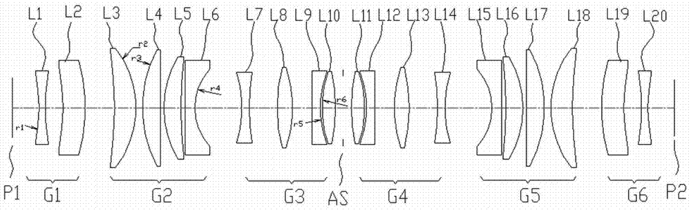
[0026] see figure 1 , which is a schematic structural diagram of a symmetrical bi-telecentric projection optical system provided in a preferred embodiment of the present invention. The symmetrical bi-telecentric projection optical system is used to image the graphics in the object plane P1 (Object) into the image plane P2 (image). The symmetrical bi-telecentric projection optical system sequentially includes a front group, an aperture stop AS and a rear group along the direction of its optical axis, that is, from the object plane P1 to the image plane P2. The symmetrical bi-telecentric projection...


PUM


Abstract

The invention discloses a symmetrical double telecentric projection optical system and a photoetching apparatus. The projection optical system is used for imaging patterns in an object plane into an image plane and comprises a front group, an aperture diaphragm and a rear group in the optical axis direction of the projection optical system. The front group comprises a first lens group, a second lens group and a third lens group; the first lens group has negative power, while the second lens group and the third lens group have positive power; the rear group comprises a fourth lens group, a fifth lens group and a sixth lens group; the fourth lens group and the fifth lens group have positive power, while the sixth lens group comprises negative power; the front group and the rear group are symmetrical about the aperture diaphragm and in a certain relation to each other. The projection optical system is capable of effectively correcting various optical aberrations, enlarging the image space field of view and increasing the imaging resolution ratio even though an optical material excellent in properties is used; besides, the lenses are small in aperture and no aspheric lens is adopted, and therefore, the difficulty and costs of processing, detection, and assembling and calibration can be greatly reduced.

Description

technical field [0001] The present invention relates to an optical system of a lithographic equipment for microfabrication, in particular to a symmetrical bi-telecentric projection optical system and a lithographic equipment using the symmetrical bi-telecentric projection optical system, the symmetrical bi-telecentric projection optical system The projection optical system is mainly used in micro-electromechanical systems (MEMS, Micro-Electro-Mechanical System), photolithography systems such as semiconductors, solar cells, liquid crystals, and printed circuit boards, as well as projection optical systems for photolithography. Background technique [0002] With the development of projection lithography technology, the performance of the projection optical system is gradually improved, and the projection optical system can already be applied to various fields such as circuit manufacturing. Projection lithography technology can also be used in technical fields such as semicondu...

Claims


Application Information

Patent Timeline
IPC IPC(8): G02B27/18G02B27/00G02B13/22G03F7/20
Inventor 刘鹏徐晓斌张宏张辉
Owner ZHANGJIAGANG ZHONGHE AUTOMATION TECH
Learn More