
Static-dynamic balance monitoring device for routine test centrifugal machine

A routine test and dynamic balance technology, applied in the direction of static/dynamic balance test, measuring device, machine/structural component test, etc., can solve problems such as inconvenient calculation, inaccurate estimation, complex actual structure, etc., and reduce mechanical The effect of processing amount and processing difficulty, intuitive data reading, and simple structure

Active Publication Date: 2014-10-29
GENERAL ENG RES INST CHINA ACAD OF ENG PHYSICS
View PDF5 Cites 3 Cited by
  • Summary
  • Abstract
  • Description
  • Claims
  • Application Information

AI Technical Summary

Problems solved by technology

[0005] The method of judging the static balance by installing a steel ruler on the arm is too rough to accurately judge the balance state of the arm; the dynamic monitoring method used on the geotechnical centrifuge can only reflect the dynamic unbalanced force condition. It is impossible to determine the state of static balance. We can only use theory to test balance first, and then after the centrifuge rotates to a certain speed, use dynamic monitoring data to determine whether the trim is within the allowable range. If it is not within the allowable range, it is necessary to stop and perform static trim again. The workload of the test is increased; the unbalance is judged by the method of theoretical estimation without installing a balance detection device. On the one hand, due to the complex and changeable actual structure, the calculation is inconvenient; on the other hand, the estimation is not accurate

Method used


Image

  • Static-dynamic balance monitoring device for routine test centrifugal machine
  • Static-dynamic balance monitoring device for routine test centrifugal machine
  • Static-dynamic balance monitoring device for routine test centrifugal machine

Examples


Embodiment Construction

[0021] The present invention will be further described below in conjunction with accompanying drawing:

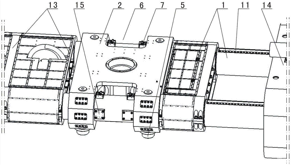
[0022] Such as figure 1 , figure 2 with image 3 As shown, in the routine test centrifuge static-dynamic balance monitoring device of the present invention, the routine test centrifuge includes a rotating arm 1, a rotating arm support 2 and a support 3, and the rotating arm 1 includes a boom and is installed respectively The test cabin 11 and the counterweight 14 at both ends of the boom, the boom includes two tension shafts 12 parallel to each other, the two tension shafts 12 are fixedly connected by a plurality of positioning rings 13, and the pivoting arm supports 2 A transverse through hole (not marked in the figure) is provided on the top, and the tension shaft 12 passes through the transverse through hole to realize connection with the pivot arm support 2, and the pivot arm support 2 is located between two adjacent positioning rings 13 so that the tension shaft 12 ...


PUM


Abstract

The invention discloses a static-dynamic balance monitoring device for a routine test centrifugal machine. The routine test centrifugal machine comprises a tumbler, a tumbler support and a machine base, the tumbler comprises a tumbler frame, a test chamber and a balancing weight, the test chamber and the balancing weight are mounted at two ends of the tumbler frame respectively, the tumbler frame comprises two tension shafts parallel to each other, the two tension shafts are fixedly connected through a plurality of retaining rings, a group of supporting seats is arranged at each of a working end and a balance weight end on the lower bottom face of the tumbler support, a rocker type sensor is mounted in each supporting seat, a group of sensor seats is mounted at the working end and the balance weight end, close to the center of the tumbler support, of the tension shafts, a pressure sensor is mounted in each sensor seat, and a stress end of each pressure sensor is in corresponding contact with the tumbler support. The static-dynamic balance monitoring device for the routine test centrifugal machine has the advantages that real-time monitoring of static weight and dynamic balance of the tumbler of the routine test centrifugal machine are achieved by the aid of the rocker type sensors and the pressure sensors respectively, and operational safety of the routine test centrifugal machine is improved.

Description

technical field [0001] The invention relates to a balance monitoring device for a routine test centrifuge, in particular to a static-dynamic balance monitoring device for a routine test centrifuge. Background technique [0002] Large-scale routine test centrifuges are widely used in national defense science and technology research and aerospace technology to carry out overload assessment or load simulation tests. This type of centrifuge has a left and right unequal long arm structure. The end of the long arm is the working end, where the test chamber or vibration table is installed. The moment of the rotating arm is balanced with respect to the central axis of rotation, that is, the center of mass of the rotating arm passes through the axis of rotation under load conditions. However, in different tests, the quality and shape of the test piece and its fixtures are different. At the same time, due to the error of static balance adjustment, it is difficult to ensure that the c...

Claims


Application Information

Patent Timeline
IPC IPC(8): G01M1/12G01M1/16
Inventor 蒋春梅洪建忠余小勇陈磊黎启胜李心耀赵宝忠吴俊
Owner GENERAL ENG RES INST CHINA ACAD OF ENG PHYSICS
Learn More