Laser dazzling shield

A laser and shield technology, applied in the direction of defense objects, etc., can solve the problems of dazzling anti-riot shields, such as heavy weight, poor endurance of dazzling functions, difficulty in holding or fighting for a long time, etc., to achieve enhanced dazzling effect, small size, and small overall volume and weight Effect

Inactive Publication Date: 2014-10-29
大连淡宁实业发展有限公司
View PDF6 Cites 1 Cited by
  • Summary
  • Abstract
  • Description
  • Claims
  • Application Information

AI Technical Summary

Problems solved by technology

[0005] Existing dazzling anti-riot shields use high-power light-emitting devices such as strong lights and strobe lights or LED arrays as dazzling light sources, which have the disadvantages of heavy weight, high power consumption, poor battery life, poor long-distance dazzling effect, and easy damage to optical components.
Mainly glare lamps and flashing lamps use high-voltage arc lamps such as mercury lamps and xenon lamps as light sources, but the luminous efficiency of arc lamps is very low, and the required power supply power is large, which leads to high power consumption of traditional dazzling anti-riot shields. Poor; the large volume of the arc lamp power supply and the large-capacity battery that powers it will cause the traditional dazzling anti-riot shield to be heavy and difficult to hold or fight for a long time
At the same time, the light divergence angle of strong lights, strobe lights and LEDs is large, and the luminous intensity of a single LED is not enough. LED arrays or area arrays are needed to achieve the required light intensity, so a large reflective bowl or beam shaping system is required to convert the light Convergence, this traditional optical structure will not only cause light energy loss of more than 10 meters and poor dazzling effect, but also there will be a large light-emitting surface (generally circular, with a radius of 30-100mm) on the shield surface, so that Dazzling light sources are easily damaged during riot control

Method used


Image

  • Laser dazzling shield
  • Laser dazzling shield
  • Laser dazzling shield

Examples


Embodiment Construction

[0030] The present invention will be described in detail below with reference to the accompanying drawings and examples.

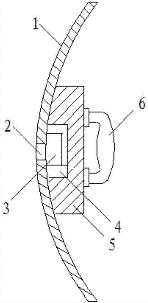
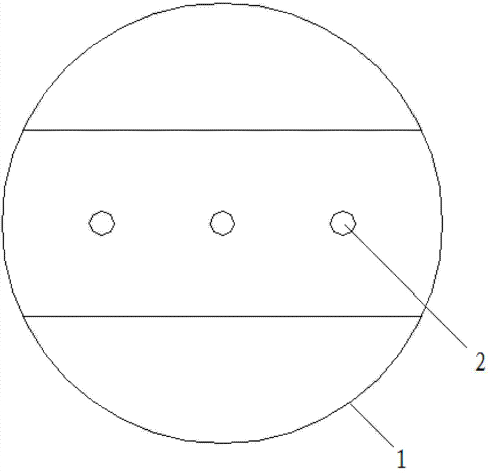
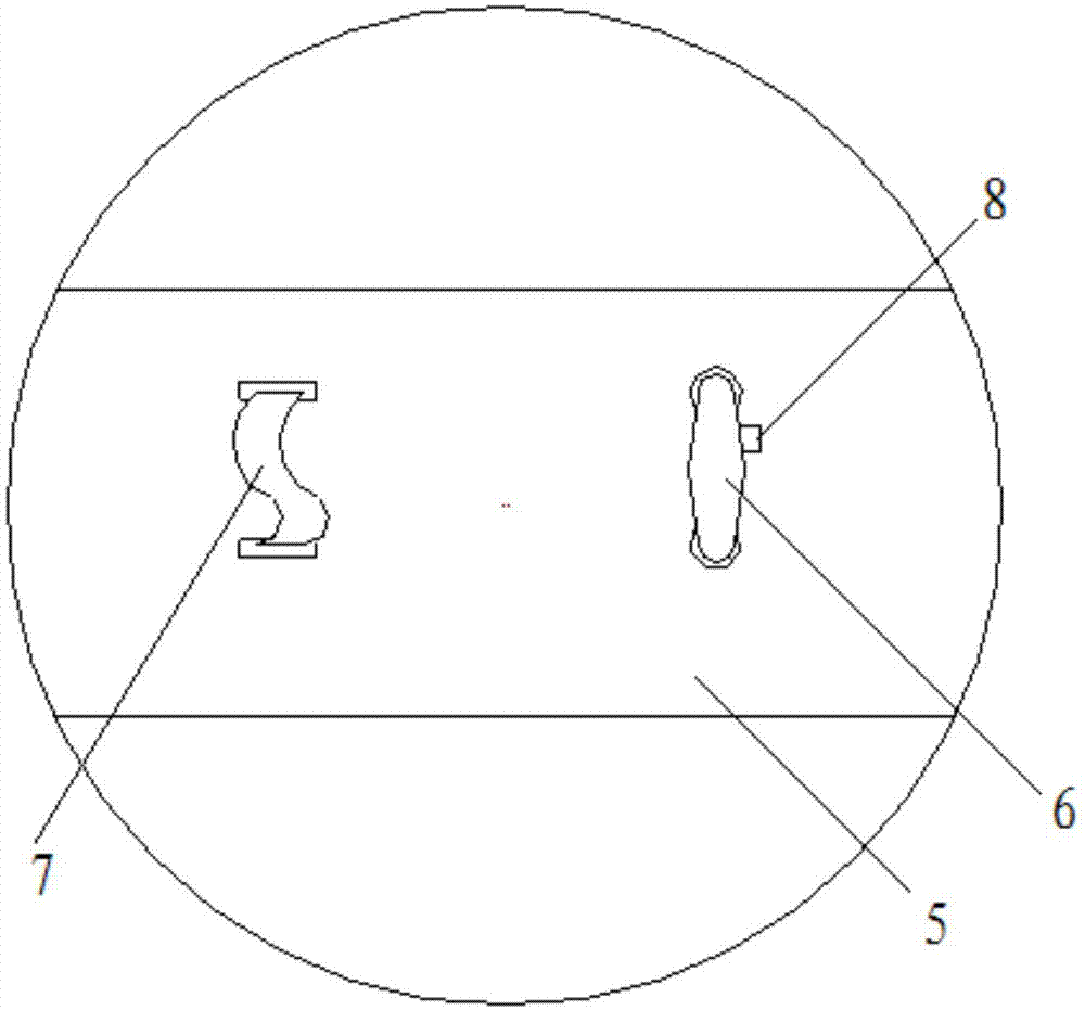
[0031] as attached figure 1 and 2 As shown, a laser dazzling shield of the present invention includes a shield 1, a laser source 3, a power supply 4, a control switch 8, a shock absorbing pad 5, an armband 6 and a handle 7;

[0032] The shield 1 is processed with three laser light exit holes 2 running through its thickness direction;

[0033] The laser source 3 is composed of a solid-state laser or a semiconductor laser and corresponding optical shaping components and power components, and the wavelength of visible laser light is 500-550nm and 600-680nm;

[0034] One side of the shock absorbing pad 5 is processed with a concave groove, and the other side is the installation plane of the control switch 8, the armband 6 and the handle 7;

[0035] The overall connection relationship is: the grooved side of the shock-absorbing pad 5 is fixedly connected to ...


PUM

PropertyMeasurementUnit
Wavelengthaaaaaaaaaa
Irradiation intensityaaaaaaaaaa
Emission wavelengthaaaaaaaaaa

Abstract

The invention discloses a laser dazzling shield and belongs to the technical field of security and photoelectricity. The laser dazzling shield comprises a shield body, a laser source, a power source, a control switch, a shock absorption pad, an arm band and a handle, wherein the laser source is composed of an all-solid-state laser or a semiconductor laser, a corresponding optical shaping assembly and a power source assembly, and emits visible lasers of which the wave lengths are 500-550 nm and 600-680 nm; the face, provided with a groove, of the shock absorption pad is fixedly connected with the inner side face of the shield body; the power source and the laser source are fixedly installed in the groove of the shock absorption pad; the emitting end of the laser source corresponding to a laser emitting hole in the shield body; the power source is connected with the laser source and provides power to the laser source; the arm band, the control switch and the handle are fixedly installed on the surface of the shock absorption pad; the control switch is installed on one side of the handle and connected with a current loop of the power source and the laser source. The laser dazzling shield is good in temporary blinding effect, the laser source is low in power consumption and long in run time, and the laser dazzling shield is simple in overall structure, light and capable of being worn for use for a long time.

Description

technical field [0001] The invention relates to a shield, in particular to a laser dazzling shield, which belongs to the field of security and photoelectric technology. Background technique [0002] The functions of the police anti-riot equipment currently equipped in large quantities in my country are too single, such as simple shields, batons, and anti-riot forks. [0003] On March 1, 2014, the appalling Kunming massacre occurred in Kunming, my country. Five thugs with knives killed more than 180 innocent citizens in a relatively short period of time. Among them, a deputy director of a police station died heroically in the process of using a riot fork to resist riots, highlighting the inadequacy of our country's police anti-riot equipment in fighting sudden violent terrorist incidents. [0004] Using visible light to dazzle mobs and make them temporarily blind and lose their attack power is currently internationally recognized as a method of anti-riot with the least harm ...

Claims


Application Information

Patent Timeline
IPC IPC(8): F41H5/08
Inventor 许江珂王戈陈浩郑帅杜雪琴
Owner 大连淡宁实业发展有限公司
Why Eureka
Try Eureka