
Light alloy semi-continuous casting device and method under composite action of shear and magnetic field

A compound effect and light alloy technology, applied in the field of light alloy semi-continuous casting, can solve the problems of reduced temperature field uniformity control ability, poor ingot resistance to cracks, weak electromagnetic field shearing effect, etc., to increase effective nucleation The effect of reducing particle size, increasing the yield, and refining the alloy structure

Active Publication Date: 2016-04-20
NORTHEASTERN UNIV LIAONING
View PDF5 Cites 3 Cited by
  • Summary
  • Abstract
  • Description
  • Claims
  • Application Information

AI Technical Summary

Problems solved by technology

On the basis of conventional semi-continuous casting, the use of electromagnetic field is increased, and the electromagnetic field is used to cause strong convection in the melt to promote the uniformity of the temperature field and reduce the internal stress. To a certain extent, the alloy structure can be refined. Ingot, due to the skin effect of the electromagnetic field in the metal, the magnetic field strength acting on the center of the ingot will be relatively weak, resulting in weakened structure refinement at the center of the ingot, and the ability to regulate the uniformity of the temperature field will be significantly reduced. Moreover, the shear effect caused by the electromagnetic field is weak, and the film-like oxide cannot be dispersed and broken into fine particles distributed separately. The larger the size of the ingot, the worse the ingot's ability to resist cracks

Method used


Image

  • Light alloy semi-continuous casting device and method under composite action of shear and magnetic field
  • Light alloy semi-continuous casting device and method under composite action of shear and magnetic field
  • Light alloy semi-continuous casting device and method under composite action of shear and magnetic field

Examples


Embodiment Construction

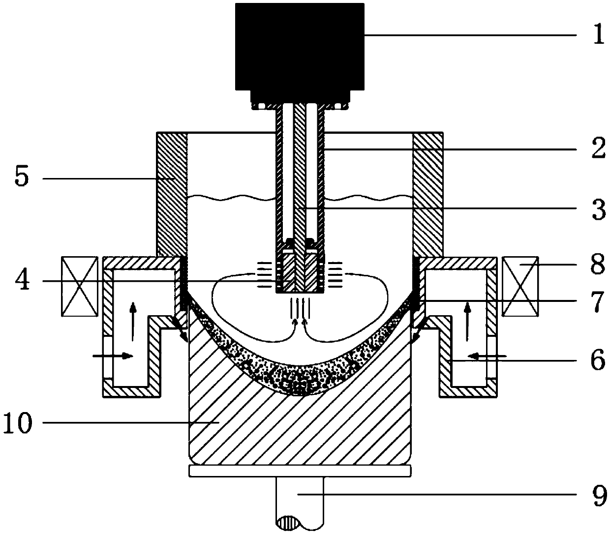
[0028] The present invention will be further described in detail below in conjunction with the accompanying drawings and specific embodiments.

[0029] Such as figure 1 As shown, a light alloy semi-continuous casting device under the compound action of shear and magnetic field includes a casting unit, and the casting unit includes a hot top 5, a crystallizer 6, a dummy ingot 9 and an induction coil 8, and the hot top 5 Located above the crystallizer 6, the induction coil 8 is arranged on the periphery of the crystallizer 6, a graphite ring 7 is arranged on the inner wall of the crystallizer 6, and the dummy ingot 9 is located below the crystallizer 6 and corresponds to the crystallizer 6; it is arranged above the casting unit There is a melt shearing unit, and the melt shearing unit includes a driving motor 1, a stator sleeve 2, a connecting shaft 3 and a shearing blade 4, the motor shaft of the driving motor 1 is connected with one end of the connecting shaft 3, and the shear...


PUM

PropertyMeasurementUnit
porosityaaaaaaaaaa
porosityaaaaaaaaaa
areaaaaaaaaaaa

Abstract

The invention discloses a light alloy semi-continuous casting device and method under the combined action of shearing and a magnetic field, and belongs to the technical field of light alloy semi-continuous casting. Compared with the prior art, the magnetic field and melt shearing are combined on the basis of conventional semi-continuous casting, a melt shearing unit has the advantages of strong shearing and weak convection current, the advantages make up the defects of weak shearing and strong convection current of the magnetic field, and accordingly strong shearing and strong convection current can be generated simultaneously in melt in the semi-continuous casting process. The requirement of a temperature field for uniformity can be completely met, breaking of dendritic crystals can be promoted, film-like oxides in the melt can be dispersed and broken to independently distributed fine particles, the alloy structure can be refined effectively, effective nucleation particles are added, damage to performance of cast ingots from flaws like film-like oxides in the melt is weakened, and the crack resistance and the yield of the cast ingots are improved.

Description

technical field [0001] The invention belongs to the technical field of semi-continuous casting of light alloys, in particular to a semi-continuous casting device and method of light alloys under the compound action of shear and magnetic field. Background technique [0002] High-strength aluminum alloy and magnesium alloy are the two most typical light alloys, and the ingot preparation link in the production process is mainly realized by semi-continuous casting. When casting high-strength light alloy ingots, especially large-scale high-strength light alloy ingots, due to their high modulus, strength and low plasticity, they are prone to hot cracking and cold cracking. Defects, once hot cracking or cold cracking occurs, the ingot material will be scrapped, reducing the yield of the ingot. [0003] Theoretically, the above-mentioned casting defects can be avoided from two aspects. One is to make the temperature field more uniform to reduce the internal stress, and the other is...

Claims


Application Information

Patent Timeline
Patent Type & Authority Patents(China)
IPC IPC(8): B22D11/11B22D11/14
Inventor 左玉波李磊朱庆丰赵志浩崔建忠
Owner NORTHEASTERN UNIV LIAONING
Learn More