
Illuminating element having a coding element

A technology of light-emitting elements and coding elements, which is applied to the semiconductor devices of light-emitting elements, light sources, light source fixing, etc., can solve the problems of expensive and non-existent electronic devices, and achieve the effect of low cost and simple structure

Inactive Publication Date: 2014-10-22
OSRAM GMBH
View PDF3 Cites 0 Cited by
  • Summary
  • Abstract
  • Description
  • Claims
  • Application Information

AI Technical Summary

Problems solved by technology

Such electronic components are relatively expensive and usually require a certain installation space, which is usually not available in LED modules or is required for other purposes, for example for cooling

Method used


Image

  • Illuminating element having a coding element
  • Illuminating element having a coding element

Examples


Embodiment Construction

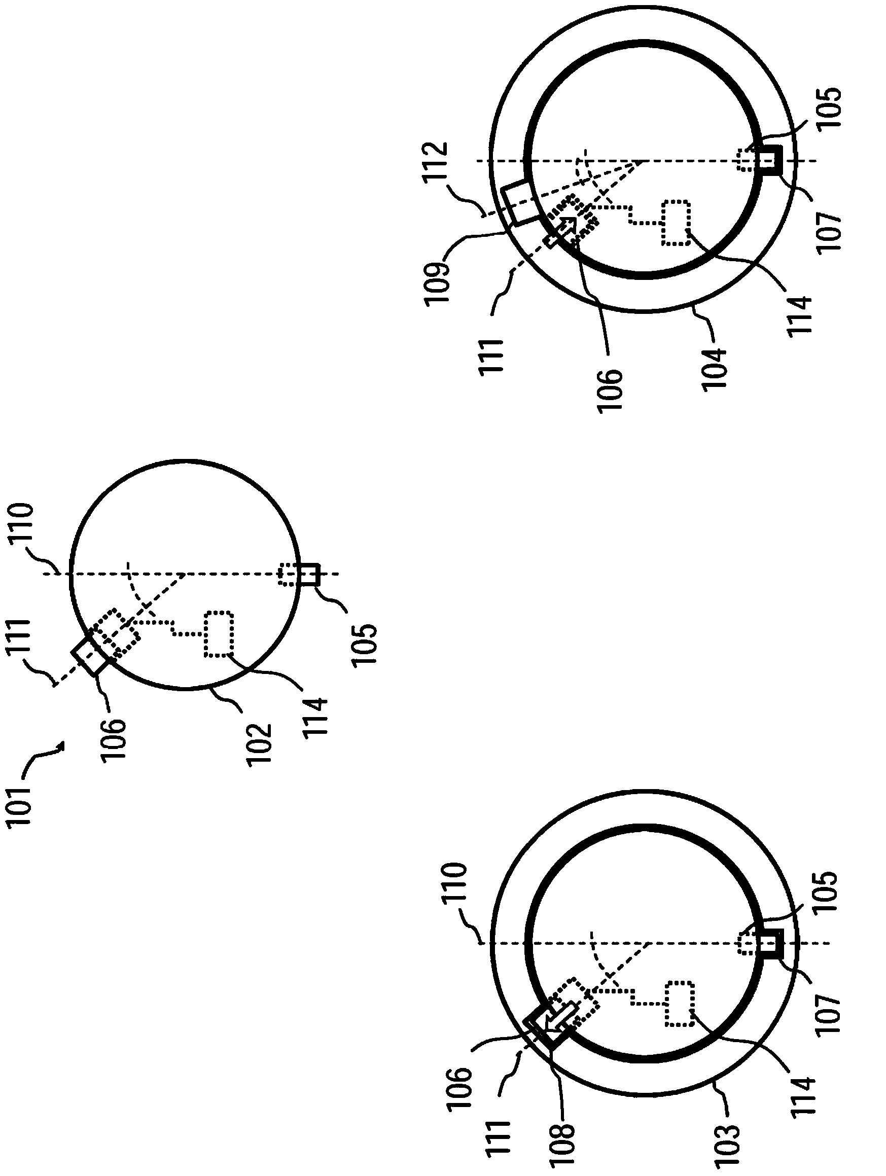
[0025] figure 1 In the upper center, a luminous element 101 is shown in an exemplary underside view of a base 102 of the luminous element. In addition to the schematically drawn components, the luminous element 101 also has further components, such as at least one bulb, in particular a semiconductor luminous element, light emitting diodes (LEDs) and contact elements on the base 102 for applying current or voltage.

[0026] The luminous element 101 can be inserted by means of its base 102 into differently designed lamp holders 103, 104, as in figure 1 as sketched in the lower left or lower right in . The sockets 103 , 104 differ, for example, in that they supply different voltages and apply them to the contact elements of the inserted luminous element 101 . For example, the first lamp socket 103 provides a voltage of 220V and the second lamp socket 104 provides a voltage of 110V.

[0027] In order to prevent unintentional insertion of wrong lighting elements, the sockets 103...


PUM


Abstract

An illuminating element (101) having at least one coding element (105, 106) is proposed, wherein a mode of operation of the illuminating element (101) can be set on the basis of the switching state of at least one adjustable coding element (106) of this type.

Description

technical field [0001] The invention relates to a lighting element having at least one coding element. Background technique [0002] Known as illuminants are so-called LED modules (LED: Light Emitting Diode; an LED module comprising, for example, at least one semiconductor light-emitting element and, for example, at least one further functional element, such as an electronic, optical or mechanical component). In the case of such an LED module with a lamp holder adapted thereto, for example for installation in a luminaire, several variants can be provided. In particular, variants for different grid voltages are possible. Since the electronics used in the illuminants or modules must be designed for a specific input voltage, the modules and lampholders are protected against unintentional replacement by means of coding elements. A module of one variant is therefore only adapted to the corresponding associated lampholder and not to a lampholder of the other variant. [0003] D...

Claims


Application Information

Patent Timeline
Patent Type & Authority Applications(China)
IPC IPC(8): F21K99/00F21V17/00F21V23/04
CPCF21K9/00F21V23/04F21V17/005F21Y2115/10F21K9/232
Inventor 斯特凡·洛伦茨
Owner OSRAM GMBH
Learn More