
Method for avoiding pump surges in a compressor

A compressor and turbine technology, applied in the field of avoiding pump surge in compressors, to achieve the effect of reducing pressure ratio, avoiding indirect damage, and reducing compressor pressure ratio

Active Publication Date: 2014-10-22
SIEMENS ENERGY GLOBAL GMBH CO & KG
View PDF8 Cites 4 Cited by
  • Summary
  • Abstract
  • Description
  • Claims
  • Application Information

AI Technical Summary

Problems solved by technology

On the downside, however, such sensors have only a limited lifetime at higher ambient temperatures

Method used


Image

  • Method for avoiding pump surges in a compressor

Examples


Embodiment Construction

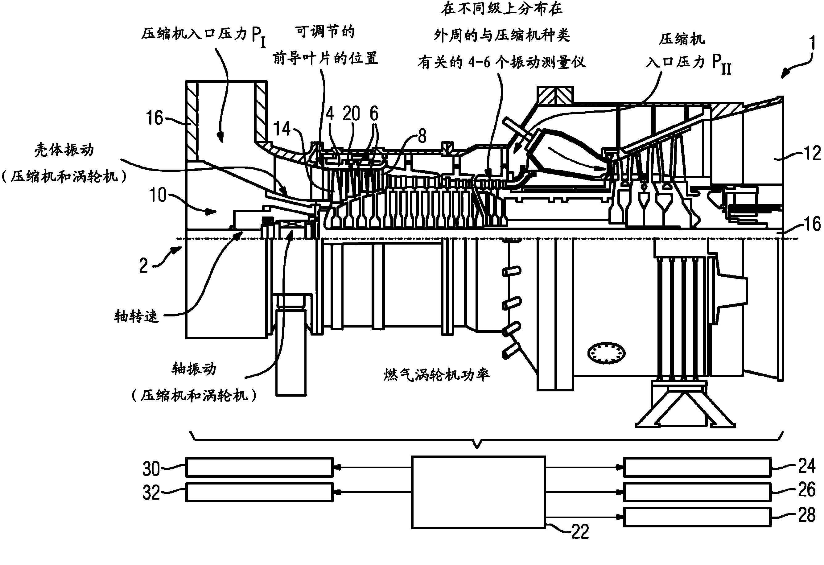
[0024] The fluid machine 1 partially shown in this drawing is designed as a gas turbine. Only the compressor 2 of the gas turbine is shown. The compressor 2 comprises guide vanes 6 fixed on the housing 4 and thus stationary, which are located in the flow channel 8 between the compressor inlet 10 and the compressor outlet 12 . The first guide vanes 6 in the flow direction of the air are designed as adjustable leading guide vanes 14 . As a result, the air quantity fed into the flow channel 8 can be adjusted and throttled.

[0025] Behind each guide blade 6 , 14 in the flow direction of the air, a rotor blade 18 is provided on the shaft 16 . The rotor blades 18 and the guide blades 6 , 14 are respectively arranged in a star-shaped ring in the flow channel 8 . The ring formed by the guide blades 6 , 14 together with the downstream ring formed by the rotor blades in the flow direction each form a stage of the compressor 2 .

[0026] In order to detect a threatening surge at an ...


PUM


Abstract

The method involves monitoring multiple parameters of the compressor during the operation. The target value range for the multiple parameters is determined. A reaction counteracting the pump thrust is triggered during overshooting or undershooting of the parameters from the target value range. The multiple parameters comprise a parameter assigned to the rotary sound of a compressor (2). The parameter assigned to the rotary sound of the compressor is an oscillation-amplitude or frequency of a component of a turbo engine (1). An independent claim is included for a compressor with control having sensors.

Description

technical field [0001] The invention relates to a method for avoiding pump surge in a compressor, in which a plurality of characteristic parameters of the compressor are monitored during operation and setpoint value ranges for the plurality of characteristic variables are preset, wherein in The anti-pump surge response is triggered when the value of the characteristic parameter is above or below the setpoint range. The invention also relates to a compressor and a fluid machine with a compressor and a control device, which is connected on the data input side to a plurality of sensors designed to detect characteristic variables during operation. Background technique [0002] Compressors, especially gas turbines, are prone to surge under defined operating conditions. If the counterpressure is too high in the direction of flow, it is no longer possible for the compressor to deliver air and the direction of flow is partially or even completely reversed. With partial backflow, a...

Claims


Application Information

Patent Timeline
Patent Type & Authority Applications(China)
IPC IPC(8): F04D27/00F02C9/24
CPCF04D27/001
Inventor C.格雷维
Owner SIEMENS ENERGY GLOBAL GMBH CO & KG
Learn More