
Patch switch and control system thereof

A patch and switch technology, applied in the field of patch switches and their control systems, can solve problems such as inconvenient use for children, danger of electric shock for users, and easy hidden dangers, etc., and achieve the goals of shortening the construction period, saving labor, and saving wiring costs Effect

Active Publication Date: 2014-10-22
深圳市爱峰高科科技有限公司
View PDF6 Cites 0 Cited by
  • Summary
  • Abstract
  • Description
  • Claims
  • Application Information

AI Technical Summary

Problems solved by technology

[0002] Traditional switches and smart switches on the market can only be installed on the wall and cannot be moved, which is very inconvenient
The switches are all boxed, and slots must be opened inside the wall, and the circuit is pre-embedded in the wall to connect with various electrical appliances; since the switch is fixed on the wall, only people can walk to the switch to operate it. It is very inconvenient for children to use; if two or more switches are set for the same electrical appliance, the pre-embedded circuit will be very complicated, unsightly and likely to cause hidden dangers
At present, there is a smart switch that can be controlled by a mobile phone, but because the control module needs power supply, it needs to design a special circuit to realize it. At present, the existing smart switch on the market uses a parallel capacitor or other modules to obtain power. The disadvantage is that it can only work when the light is off, and stop working when the light is on, and the current of the parallel power supply module when the light is off causes 220V voltage to exist on the lamp holder, which may cause electric shock hazards to users

Method used


Image

  • Patch switch and control system thereof
  • Patch switch and control system thereof
  • Patch switch and control system thereof

Examples


Embodiment Construction

[0032] Below in conjunction with accompanying drawing, the present invention is described in more detail:

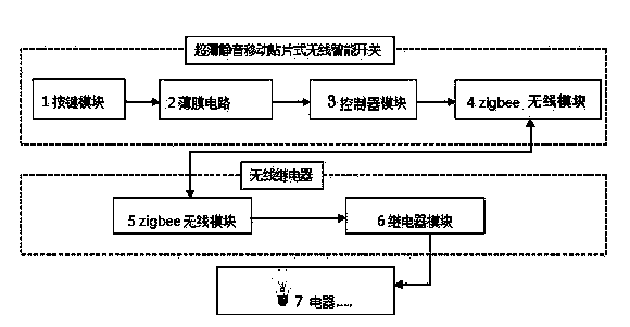
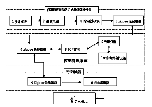
[0033] The present invention provides a patch switch, comprising a shell connected to the wall surface of the structural material, a control communication module, a thin film circuit module 2 and a key module 1; Button module 1; the button module 1 is connected to the shell through the first rotating shaft, and the rear side of the button module 1 is provided with a thin film circuit 2, and the thin film circuit 2 is provided with contacts, brackets and elastic conductors, and the elastic conductors It is arranged in the bracket, and the position corresponds to the electric shock position. The bracket is connected to the thin film circuit 2 through the second rotating shaft; the first rotating shaft is in the same direction as the second rotating shaft, and the button module 1 contacts the thin film circuit 2 through the elastic conductor; It is characterized in that: th...


PUM

PropertyMeasurementUnit
Thicknessaaaaaaaaaa
Thicknessaaaaaaaaaa

Abstract

The invention discloses a patch switch and a control method thereof. The patch switch comprises a patch switch body, a server module and an equipment end; the switch is an ultra-thin intelligent switch patch capable of being controlled remotely in a wireless mode; the equipment end is provided with a wireless module and a relay module; the wireless module is used for receiving wireless signals sent from the patch switch body or the server module, and the relay module controls the on and off of an electric appliance; the server module comprises a coordinator, a gateway, a server and a mobile equipment terminal. The mobile patch type wireless intelligent switch changes the traditional illumination wire arrangement mode, a user does not need to open walls and cut holes to arrange pipelines and wires, the manpower, physical resource and financial resource cost is saved, and the construction period is shortened; the patch switch communicates with mobile equipment with a special software through the wireless network, based on a zigbee communication technology, the patch switch can be controlled remotely, turned on / off regularly and automatically and notify the status, a lamp is turned off by one click, the energy is saved, and the low-carbon life is completely realized.

Description

technical field [0001] The invention relates to the technical field of electrical switches, in particular to a patch switch and a control system thereof. Background technique [0002] Traditional switches and smart switches on the market can only be installed on the wall, which is very inconvenient if they cannot be moved. The switches are all boxed, and slots must be opened inside the wall, and the circuit is pre-embedded in the wall to connect with various electrical appliances; since the switch is fixed on the wall, only people can walk to the switch to operate it. It is very inconvenient for children to use; if two or more switches are to be set for the same electrical appliance, the pre-embedded circuit will be very complicated, unsightly and likely to cause hidden dangers. At present, there is a smart switch that can be controlled by a mobile phone, but because the control module needs power supply, it needs to design a special circuit to realize it. At present, the e...

Claims


Application Information

Patent Timeline
IPC IPC(8): G05B19/04G08C17/02H04L29/06
Inventor 陈峰
Owner 深圳市爱峰高科科技有限公司
Learn More