A cutter head structure for tbm

A cutter head and hob technology, which is applied in mining equipment, earth-moving mining, tunnels, etc., can solve the problems of small excavation area, low rock breaking efficiency, short service life, etc., so as to reduce the degree of wear and improve the excavation efficiency. , Improve the effect of rock breaking efficiency

Active Publication Date: 2016-10-26
CHINA RAILWAY TUNNEL GROUP CO LTD +1
View PDF7 Cites 0 Cited by
  • Summary
  • Abstract
  • Description
  • Claims
  • Application Information

AI Technical Summary

Problems solved by technology

The commonly used cutter head is a planar structure, the excavation area is small, the number of disc-shaped hobs on the cutter head is small, and the rock breaking efficiency is low, and the rock can only be cut and broken by the disc-shaped hob. Therefore, the disc-shaped The hob is subject to a large torque during this process, which is easy to wear and has a short service life

Method used


Image

  • A cutter head structure for tbm
  • A cutter head structure for tbm

Examples


Embodiment Construction

[0015] The present invention will be further described through specific embodiments below in conjunction with the accompanying drawings.

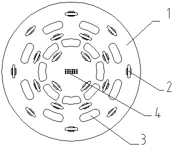
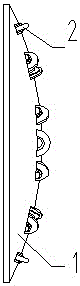
[0016] As shown in the figure, a cutterhead structure for TBM, one side of the cutterhead body 1 is fixed on the TBM body, the working surface on the other side is a spherical surface, a central mounting hole is set at the apex of the working surface, and A center hob unit 4 is arranged in the center mounting hole, and the center hob unit 4 is formed by connecting four hobs sequentially through the cutter shaft. On the working surface of the cutter head body 1, the The central axis is the center of the circle, and a plurality of installation holes are evenly arranged on multiple circles with different radii, and an earth-rock discharge hole 3 for earth-rock discharge is evenly arranged between two adjacent rings of installation holes, and an earth-rock discharge hole 3 is arranged in the installation holes respectively. To break the hob 2 o...


PUM


Abstract

A cutterhead structure for TBM, one side of the cutterhead body is fixed on the TBM body, the working surface on the other side is a spherical surface, a central mounting hole is set at the apex of the working surface, and a central mounting hole is set in the central mounting hole For the center hob unit, on the working surface of the cutterhead body, with the central axis of the cutterhead body as the center, a plurality of mounting holes are uniformly arranged on multiple circles with different radii, and between two adjacent rings of mounting holes Earth and rock discharge holes for earth and rock discharge are evenly arranged, and hobs for breaking rock mass are respectively arranged in the installation holes. The invention improves the structure of the cutterhead and optimizes the layout of the hobs to increase the excavation area of ​​the rock-breaking cutterhead and increase the number of arranged hobs, so as to improve the rock-breaking efficiency and reduce the torque and thrust of the cutterhead.

Description

technical field [0001] The invention belongs to the technical field of rock breaking, and mainly relates to a cutter head structure used for TBM. Background technique [0002] TBM is a full-face hard rock tunneling machine, which can realize the processes of tunneling, support, slag discharge and other processes and operate continuously. It has the advantages of fast tunneling speed, environmental protection, and high comprehensive benefits. It can realize deep burial in complex geographical features that are difficult to achieve by traditional drilling and blasting methods. In the construction of long tunnels, under the action of thrust, the disc-shaped hob installed on the cutter head presses against the rock surface. With the rotation of the cutter head, the disc-shaped hob revolves around the central axis of the cutter head and rotates around its own axis at the same time. Under the strong thrust and torque of the cutter head, the hob rolls on the fixed concentric slit o...

Claims


Application Information

Patent Timeline
Patent Type & Authority Patents(China)
IPC IPC(8): E21D9/11
Inventor 常家东王海霞
Owner CHINA RAILWAY TUNNEL GROUP CO LTD
Why Eureka
Try Eureka