Micro-bubble generator

A technology of microbubble generator and vibration exciter, applied in solid separation, flotation water/sewage treatment, animal husbandry, etc. The effect of the probability of small mergers

Inactive Publication Date: 2014-10-22
CHONGQING THREE GORGES UNIV
View PDF4 Cites 3 Cited by
  • Summary
  • Abstract
  • Description
  • Claims
  • Application Information

AI Technical Summary

Problems solved by technology

[0006] The purpose of the present invention is to provide a microbubble generator to solve the problem of high energy consumption of the existing microbubble generator and the easy aggregation of microbubbles leading to excessively large microbubble diameters

Method used


Image

  • Micro-bubble generator
  • Micro-bubble generator

Examples


Embodiment Construction

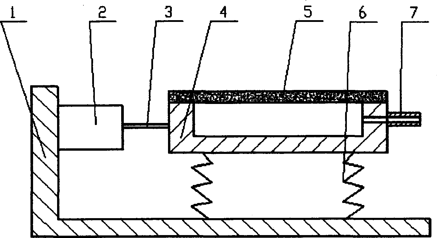
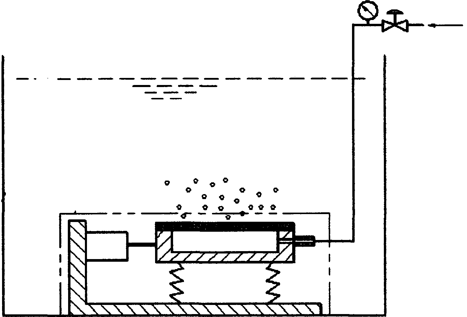
[0023] Such as figure 1 As shown, a microbubble generator includes a base 1 , an exciter 2 , a connector 3 , a chamber tank 4 , a microporous material 5 , a pressure gas inlet pipe 7 , and a flexible support 6 . The vibrator 2 is fixed on the base 1, the microporous material 5 is fixed on the chamber groove 4 to form a chamber, the vibrator 2 and the chamber groove 4 are connected by a connecting piece 3, and the chamber groove 4 is connected by a flexible support 6 Fixed on the base 1, the pressure gas inlet pipe 7 is fixed on the chamber groove 4 and communicates with the chamber.

[0024] In order to facilitate the control of gas parameters in the chamber, an air flow controller and a pressure gauge are provided on the pressure gas inlet pipe 7 .

[0025] The micropore diameter of the microporous material is 0.1 μm to 100 μm. Of course, the diameter of the microholes can also be adjusted according to actual needs.

[0026] In this embodiment, the base 1 is composed of a...


PUM

PropertyMeasurementUnit
diameteraaaaaaaaaa
diameteraaaaaaaaaa
diameteraaaaaaaaaa

Abstract

The invention discloses a micro-bubble generator which comprises a base, a vibration exciter, a connecting piece, a cavity tank, a porous material, a pressure gas inlet tube and a flexible support, wherein the vibration exciter is fixedly arranged on the base; the porous material is fixedly arranged on the cavity tank to form a cavity; the vibration exciter and the cavity tank are connected by virtue of the connecting piece; the cavity tank is fixedly arranged on the base by virtue of the flexible support; the pressure gas inlet tube is fixedly arranged on the cavity tank and is communicated with the cavity. According to the micro-bubble generator, micro-bubbles enter water when the micro-bubbles do not grow to be contacted with adjacent micro-bubbles, the probability of merging the micro-bubbles is greatly reduced, and micro-bubbles with ideal sizes can be obtained. Small micro-bubbles can be generated under large micro-pore diameter, frictional loss between gas and micro-pores is reduced, the cost of the generated micro-bubbles is low, and the air void can be controlled by enlarging the external surface area of the porous material and prolonging the time. Moreover, the obtained micro-bubbles can be wide in diameter range by adjusting the shear velocity, pore diameter and air pressure in the cavity, and the micro-bubble generator is suitable for various different working conditions.

Description

technical field [0001] The invention belongs to the field of microbubble generators and is applicable to various fields such as air flotation water purification, mineral flotation, slag removal in food industry, and aeration in aquaculture. Background technique [0002] The widespread use of mineral floatation in the 19th century led people to think of using the same principle to purify sewage. In the 1930s, reports of air flotation water purification appeared. With the deepening of research, in the 1950s, the use of air flotation Large-scale drinking water purification has been widely used in many countries. The diameter of microbubbles suitable for water treatment is generally 10-80 microns. At present, the diameter of microbubbles precipitated by the dissolved air method widely used in air flotation water purification is between 10-120 microns, but the equipment requires complete airtightness, making Process equipment is more complex. Both electrolysis and ultrasonic fo...

Claims


Application Information

Patent Timeline
Patent Type & Authority Applications(China)
IPC IPC(8): C02F1/24B03D1/02A01K63/04
Inventor 张卫王海宝赵英杰徐海华王浩匡亚林
Owner CHONGQING THREE GORGES UNIV
Why Eureka
Try Eureka