
Enhanced photon detection device with biased deep trench isolation

A technology of deep trench isolation and photon detection, applied in the field of photodiodes in photon sensors, can solve the problems of increasing dark current rate, sacrificing fill factor, increasing area, etc.

Active Publication Date: 2014-10-15
OMNIVISION TECH INC
View PDF4 Cites 45 Cited by
  • Summary
  • Abstract
  • Description
  • Claims
  • Application Information

AI Technical Summary

Problems solved by technology

Known designs that form guard rings or isolation increase the area per pixel cell and sacrifice fill factor
Additionally, as image sensors are miniaturized, the pixel cells contained therein suffer from increased dark current rates

Method used


Image

  • Enhanced photon detection device with biased deep trench isolation
  • Enhanced photon detection device with biased deep trench isolation
  • Enhanced photon detection device with biased deep trench isolation

Examples


Embodiment Construction

[0011] In the following description, numerous specific details are set forth in order to provide a thorough understanding of the present invention. It will be apparent, however, to one skilled in the art that the specific details need not be employed to practice the invention. In other instances, well-known materials or methods have not been described in detail so as not to obscure the present invention.

[0012] Reference in this specification to "one embodiment," "an embodiment," "an example," or "an example" means that a particular feature, structure, or characteristic described in connection with the embodiment or example is included within the scope of the present invention. In at least one embodiment. Thus, appearances of the phrases "in one embodiment," "in an embodiment," "an example," or "an example" in various places in this specification are not necessarily all referring to the same embodiment or example. Furthermore, the particular features, structures or charact...


PUM


Abstract

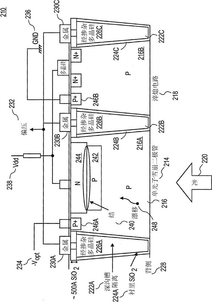
The invention relates to an enhanced photon detection device with biased deep trench isolation. The photon detection device includes a photodiode having a planar junction disposed in a first region of semiconductor material. A deep trench isolation (DTI) structure is disposed in the semiconductor material. The DTI structure isolates the first region of the semiconductor material on one side of the DTI structure from a second region of the semiconductor material on another side of the DTI structure. The DTI structure includes a dielectric layer lining an inside surface of the DTI structure and doped semiconductor material disposed over the dielectric layer inside the DTI structure. The doped semiconductor material disposed inside the DTI structure is coupled to a bias voltage to isolate the photodiode in the first region of the semiconductor material from the second region of the semiconductor material.

Description

technical field [0001] The present invention relates generally to photodiodes, and more particularly, the present invention is directed to photodiodes for use in photonic sensors. Background technique [0002] An image capture device includes an image sensor and an imaging lens. The imaging lens focuses light onto an image sensor to form an image, and the image sensor converts the light into an electrical signal. Electrical signals are output from the image capture device to other components of the host electronic system. The electronic system may be, for example, a mobile phone, computer, digital camera or medical device. [0003] There is a continuing need to reduce the size of image sensors, which results in smaller pixel units for image sensors with the same resolution. One type of photodetector that can be used in an image sensor or in a photodetector is a single photon avalanche diode (SPAD). SPADs typically require guard rings or isolation to overcome the problems...

Claims


Application Information

Patent Timeline
IPC IPC(8): H01L27/146G01T1/29
CPCH01L27/1463H04N5/361H01L31/02H01L27/14643H01L31/02027H01L31/107H04N25/63
Inventor 张博微林志强
Owner OMNIVISION TECH INC
Learn More