
Straightly-jacking and obliquely-drawing device for injection mould

A technology of injection mold and straight top, which is applied in the field of injection mold straight top and inclined drawing device, which can solve the problems of increasing cost, occupying a large internal space of the mold, and high cost

Active Publication Date: 2014-10-15
NINGBO YUEFEI MOLD
View PDF7 Cites 8 Cited by
  • Summary
  • Abstract
  • Description
  • Claims
  • Application Information

AI Technical Summary

Problems solved by technology

[0002] The injection mold is provided with an oblique core-pulling block at the oblique hole, oblique rib or undercut structure of the molded injection molded product. The core-pulling of the oblique core-pulling block is demoulded. Top core-pulling or cable-pull core-pulling demoulding, whether it is a slanted top or a slanted pull device, needs to occupy a large internal space of the mold, resulting in an increase in the shape of the mold and an increase in cost. Big, high-cost problems and deficiencies

Method used


Image

  • Straightly-jacking and obliquely-drawing device for injection mould
  • Straightly-jacking and obliquely-drawing device for injection mould
  • Straightly-jacking and obliquely-drawing device for injection mould

Examples


Embodiment Construction

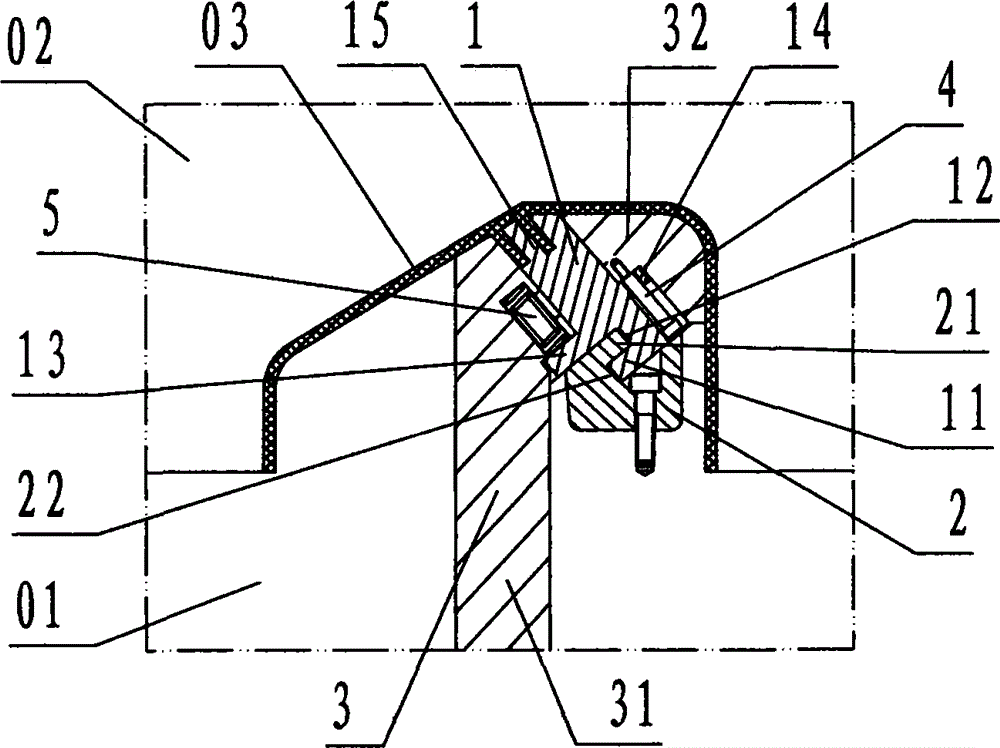
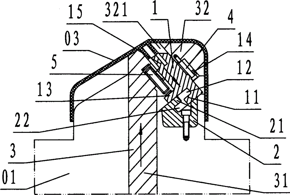
[0021] refer to Figure 1 ~ Figure 4 , an injection mold straight top and inclined pulling device of the present invention, comprising an oblique core block 1, an oblique pull block 2, a straight top core block 3, a limit rod 4, and a spring 5, wherein: the oblique core block 1 It is a block-shaped steel member with a rectangular cross-section. The left part of the inclined core block 1 is provided with a profile 15 of the oblique rib structure of the molded product 03, and the right part of the inclined core block 1 is provided with an upwardly protruding rectangular shape. The boss is called the limiter 14, and the center of the limiter 14 is provided with a circular through hole in the left and right directions called the guide hole 141, and the right part of the oblique core block 1 is provided with a downwardly protruding rectangular protrusion. The platform is called the pushing platform 13, and an upwardly recessed groove is also provided under the right part of the obl...


PUM


Abstract

The invention discloses a straightly-jacking and obliquely-drawing device for an injection mould. The device comprises an obliquely-drawing core block (1), an obliquely pulling block (2), a straightly-jacking core block (3), a limiting rod (4) and a spring (5). The obliquely-drawing core block is provided with a buckle head A and a buckle groove A; the obliquely pulling block is provided with a buckle head B and a buckle groove B; an oblique slideway is formed in a straightly-jacking mould core of the straightly-jacking core block; the obliquely-drawing core block slides into the oblique slideway , and the obliquely pulling block is positioned right below the obliquely-drawing core block and is connected with the buckle groove B by the buckle head A in a sliding and buckling manner and with the buckle groove A by the buckle head B in a sliding and buckling manner; the obliquely-drawing core block, the obliquely pulling block and the straightly-jacking core block are positioned in a mounting groove hole of a movable mould core, the obliquely pulling block and the movable mould core are fixedly connected, and the straightly-jacking core block and the movable mould core are connected in a sliding manner; when the core is drawn, the straightly-jacking core block directly jacks upwards a product to demould, and at the same time, under the action of the buckle head A, the buckle groove A, the buckle head B and the buckle groove B, the obliquely-drawing core block is rightwards, downwards and obliquely drawn from the product, and the obliquely-drawing core block is released from the obliquely pulling block; after the obliquely-drawing core block stops, the straightly-jacking core block continuously jacks and pushes the product to be released from the movable mould core; through the adoption of the technical schemes of straightly-jacking and obliquely-drawing, the injection mould required to be obliquely drawn achieves the purposes of body shrinkage and cost reduction.

Description

technical field [0001] The invention relates to an oblique drawing and demoulding device for an injection mold, in particular to an injection mold straight-top oblique device for demoulding an oblique core-pulling block embedded in a product oblique hole, oblique rib or undercut structure. pumping device. Background technique [0002] The injection mold is provided with an oblique core-pulling block at the oblique hole, oblique rib or undercut structure of the molded injection molded product. The core-pulling of the oblique core-pulling block is demoulded. Top core-pulling or cable-pull core-pulling demoulding, whether it is a slanted top or a slanted pull device, needs to occupy a large internal space of the mold, resulting in an increase in the shape of the mold and an increase in cost. Large, high-cost problems and deficiencies. Contents of the invention [0003] Aiming at the problems and deficiencies in the above-mentioned prior art, the present invention adopts a d...

Claims


Application Information

Patent Timeline
Patent Type & Authority Applications(China)
IPC IPC(8): B29C45/33B29C45/40
CPCB29C45/33B29C45/40
Inventor 胡向荣孔祥松余绍伟吴剑丰魏军辉
Owner NINGBO YUEFEI MOLD
Learn More