Chip pin pulling device

A chip tube and protruding teeth technology, which is applied in the field of chip pin removal device, can solve problems such as difficulty in pulling out pins, and achieve the effects of increasing hand feeling comfort, simple operation, and increasing distance

Inactive Publication Date: 2014-10-15
SICHUAN KAIMING INVESTMENT
View PDF0 Cites 2 Cited by
  • Summary
  • Abstract
  • Description
  • Claims
  • Application Information

AI Technical Summary

Problems solved by technology

[0004] The purpose of the present invention is to provide a device for removing chip pins, which solves the problem that the current electronic chip pins are difficult to pull out, and uses the pins of electronic chips as small welding pins for automotive sensors to achieve the purpose of reducing costs

Method used


Image

  • Chip pin pulling device

Examples


Embodiment

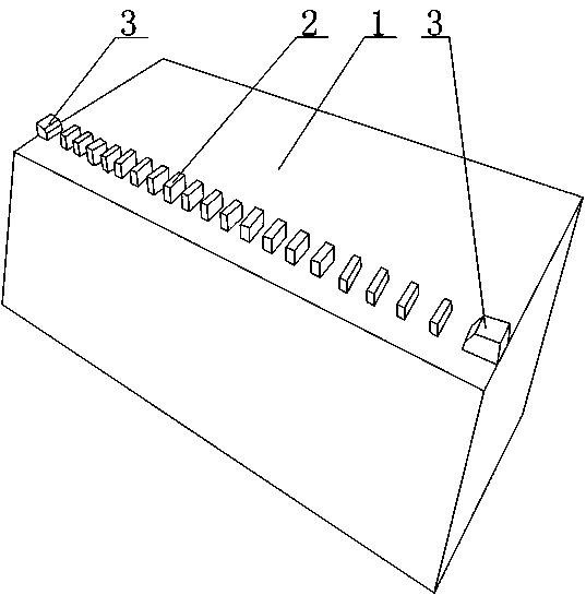
[0019] Such as figure 1 As shown, the chip pin extraction device of the present invention includes a cuboid base 1 as a whole, and a row of protruding teeth 2 protruding from the upper surface of the base 1 is arranged on the top of the base 1. The protruding teeth 1 are in the form of a cuboid as a whole. The edges and corners between the upper surface and the side of the tooth 2 are removed to form a smooth arc surface, the convex teeth 2 are evenly distributed on a straight line, and the distance from the side of the base 1 is the same, and the two ends of a row of convex teeth 2 are respectively provided with Anti-drop teeth 3, the height of anti-drop teeth 3 is slightly higher than the height of convex teeth 2, meanwhile, the width and length of anti-drop teeth 3 are slightly larger than the width and length of convex teeth 2.


PUM


Abstract

The invention discloses a chip pin pulling device. The chip pin pulling device comprises a rectangular substrate, wherein a row of convex teeth protruding on the upper surface of the substrate are arranged on the top of the substrate and are uniformly distributed on one straight line; the distance from each convex tooth to the side surface of the substrate is the same. The chip pin pulling device is very high in pulling speed, the speed for pulling pins by an operator can be up to 90 pieces per minute, the problem that a chip pin is difficultly pulled out is solved, and the production cost is reduced by taking the chip pin as a sensor welding needle; due to the fact that the structural form that anti-falling teeth are respectively arranged at the two ends of the convex teeth is adopted, the probability that the convex teeth are collided is reduced, the convex teeth are well protected, and the chip pin pulling device is simple in structure and convenient to use.

Description

technical field [0001] The invention relates to an auxiliary tool used in the sensor manufacturing industry, in particular to a device for pulling out chip pins. Background technique [0002] The automobile wheel speed sensor is mainly composed of induction head, wiring harness and accessories. The role of the induction head is to cooperate with the target gear installed on the chassis of the car to measure the speed of the car wheel, which is composed of coils, magnetic poles and other parts. On this basis, to ensure the normal operation of the sensor, the sensor must be properly installed on the chassis of the car, and there are many ways to install it. Now commonly used a kind of wheel speed sensor is to rely on the outer steel casing of the induction head to cooperate with a part, i.e. the elastic bush, and pack into the corresponding mounting hole of the chassis. When designing the sensor, it is necessary to combine the magnetic steel and the magnetic conductor in the...

Claims


Application Information

Patent Timeline
Patent Type & Authority Applications(China)
IPC IPC(8): B25B27/02
CPCB25B27/02
Inventor 曾维亮
Owner SICHUAN KAIMING INVESTMENT
Why Eureka
Try Eureka